Instructions and Warnings
- Read these instructions.
- Keep these instructions.
- Heed all warnings.
- Follow all instructions.
Protect your mixing console (and yourself)
- Do not block any console ventilation openings.
- Do not block the console fan openings.
- Do not block the openings on the bottom of the console.
- Do not place the console on an unstable surface
- Do not use the console near water. Do not spill liquids on the surface or into the openings.
- Only plug the unit only into a grounded outlet that complies with local norms. Never defeat the ground pin.
- Avoid placing heavy objects on the control surface, scratching the surface or touchscreen with sharp objects, or rough handling and vibration.
- Cover the mixer when it is not being used for extended periods.
- Unplug the console during lightning storms or when it is not being used for extended periods.
Pay attention to the operating environment
- Do not place the console in direct sunlight
- Do not install the console near any heat sources such as radiators, heat resistors, stoves, or other equipment (including amplifiers) that produce heat.
- If the equipment has been stored in sub-zero temperatures, allow time for it to reach normal operating temperature before use at the venue. The recommended operating temperature for eMotion LV1 Classic is 5 to 35 degrees Celsius.
Keep your eMotion LV1 Classic looking good
- Clean the console only with a dry cloth.
- Do not use chemicals, abrasives, or solvents when cleaning the console.
- Clean the screen only with products approved for touchscreens.
Service
This unit contains no user-serviceable parts. Refer all servicing to a qualified service engineer through an authorized Waves dealer. Servicing is necessary if the console has been damaged in any way, such as when liquid has been spilled into the unit, objects have fallen into it, it has been exposed to rain or moisture, it fails to operate normally, or it has been dropped.
Waves assumes no liability for damage caused by maintenance, repair or modifications performed by unauthorized personnel.
Introduction
Thank you for choosing the eMotion LV1 Classic mixing console from Waves. To work efficiently and quickly get the best results, please familiarize yourself with this user guide and keep it as a reference.
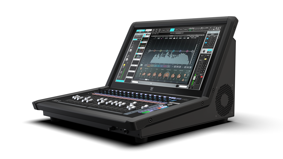
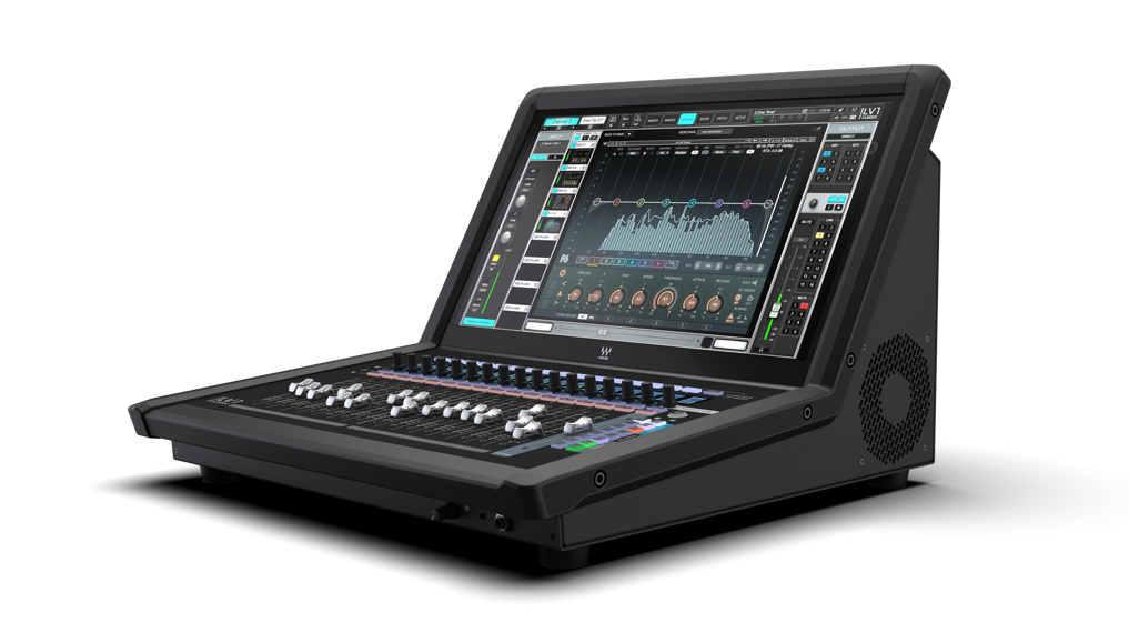
eMotion LV1 Classic is a mixing console designed for live sound, including front-of-house, monitor, and broadcast applications.
LV1 Classic provides industry-leading sound quality, seamless plugin integration, and all the functionality of a full-sized mixing console in a compact package. It can be expanded with stageboxes or other SoundGrid I/O devices. Servers can be added for extra processing power or redundancy. We recommend visiting the Waves support site: http://www.waves.com/support. There, you will find an extensive answer base, the latest technical specifications, detailed installation guides, troubleshooting help, and much more.
Waves Inc. Knoxville office: 2800 Merchant Drive, Knoxville, TN 37912. Phone: 1-865-909-9200.
Main Features
64 stereo/mono input channels, 44 buss/return channels
16 DCA faders, 8 mute groups, 18 user-assignable shortcut keys
16 Waves Signature preamps, 12 line outputs
- 16 Monitor auxes and 8 FX auxes (stereo/mono), 8 audio groups, L/R/C/Mono, 8 matrices (stereo/mono)
- 16+1 motorized faders and multipurpose encoders
- Up to 8 SoundGrid compatible plugins can be inserted on each channel.
- Built-in processors include industry-leading EQ, dynamics, real-time vocal pitch correction, dynamic EQ, and internal low-latency Intel-based Waves SoundGrid DSP server.
- I/Os and servers can easily be added and integrated with other eMotion LV1 systems.
- Dugan Speech Automixer (optional)
- eMo IEM for enhanced, immersive in-ear monitoring (optional)
- Remote mobile/tablet applications are available.
80-Channel Option
An optional 80-channel configuration provides 80 input channels with two switchable buss options.
- 16 groups, 24 auxes, 3 main outs, 8 matrix channles, cue
- 8 groups, 32 auxes, 3 main outs, 8 matrix channles, cue
Visit waves.com/support for detailed specifications.
It’s important to keep your eMotion LV1 Classic console up to date. You will periodically receive update notices from Waves with instructions. If you do not receive a notification, you can visit the Waves website for more information.
What’s Included with eMotion LV1 Classic?
What’s in the box?
- eMotion LV1 Classic 64 channel mixing console
- Power cables (2)
- Documentation
eMotion LV1 Classic includes these processors:
Additional plugins are available with Waves Live Sound perpetual plugin bundles. The entire Waves plugin catalog is available with a Waves Creative Access subscription. Refer to www.waves.com for more information.
About This User Guide
This User Guide provides detailed information on all eMotion LV1 Classic functions and controls. Like the mixer itself, the User Guide is organized first by Window, then by Page or Tab, and finally by Section and Controls.
Naming Conventions:
Window | The most comprehensive view (e.g., Mixer window, Show window, etc.). Windows can be accessed using tabs at the top of each view. |
Page | A subset of a window, usually accessed via a side tab (e.g., User I/O Settings, Channels Input A, Scenes, etc.). |
Section | An area of a page, typically defined by function (Output section, Channel aux sends section, etc.). |
Control | Any object used to change a parameter (fader, knob, button, etc.). |
Value Box | A window that displays a parameter and is usually used to adjust parameter values. |
Selected |
|
To keep things short, the eMotion LV1 Classic console is often referred to as “the console.”
Connections
Rear Panel
All connections, except headphones, are made on the rear panel.

-
Mains in: 115v/230v; 50/60 Hz, PSU on/off
-
Start/Quit, reset console, brightness
-
Mic/Line inputs x16
-
Analog outputs x 12
-
AES input/output
-
I/O status light (internal connections)
-
SoundGrid network ports (etherCON x2; RJ-45 x2)
-
HDMI for external display
-
USB ports x 6; network connection
-
XLR4 power connector for lamp
-
USB ports x 2
-
I/O Reset buttonThe I/O Reset is a recessed button that completely resets the Classic I/O device, rendering it temporarily inaccessible. Use this button only under the guidance of Waves technical support.
Front Panel
TRS 1/4” headphone jack x 1, TRS 1/8” headphone jack x 1; headphones volume control
Expanding Connections
In addition to the onboard Classic 16x12 I/O, LV1 Classic can assign and patch to up to 14 I/O devices, which can include any combination of hardware I/Os and drivers.
- A hardware I/O device can support up to 128 I/O channels, depending on the model.
- Computers using a SoundGrid ASIO/Core Audio driver can be configured for up to 128 driver channels.
Cables
When adding external devices, use a SoundGrid Ethernet switch and Cat 5e, Cat 6, or Cat 6a Ethernet cables to connect all hardware components. Cat 5 cables are not supported, and Waves does not recommend using Cat 6 etherCON connectors. Instead, use Cat 5e or Cat 6a etherCON connectors.
Use the SoundGrid network ports for SoundGrid only. Do not connect an Internet or other network connection to the Ethernet switch. Use a different port for those purposes.
Maximum Cable Lengths
Cat 5e/6/6a S/FTP
Node | Cable Length |
|---|---|
Host computer to switch | up to 100 meters |
Server to switch | up to 10 meters |
Switch to switch | up to 100 meters |
I/O device to switch | up to 100 meters |
Joints, or cable extenders, can be used, but with care, since some models do not have electrically connected shielding. Using such extenders in areas with interference may be problematic. Total cable length with the joint may not exceed the above maximum cable length per node. Additional joints may limit the effective cable runs.
Startup/Shut Down
Power up LV1 Classic using the “soft” power switch at the top of the rear panel.
To safely shut down, hold the “soft” power switch for five seconds. Alternatively, click “Shut Down” in the Setup window’s bottom left corner. It may take several seconds for all components to shut down completely.
To fully turn off the device, first complete the normal shutdown process, then switch off each power entry module. These on/off switches control the redundant power supplies; they do not power up the console.
Fader Bank

-
Channel Select ButtonClick the User button to toggle between Channel (default) and User-Assigned Keys.
-
Four-line Scribble Strip
-
Rotary EncodersControl Pan, Gain, or Plugin edit mapping.
-
Solo/Mute
-
16+1 100 mm Motorized Faders
-
Mixer Layers 1–8 Selector
-
Encoders ModeSelect Pan, Gain, or Plugin edit mode.
-
ShortcutsUser-assignable.
-
Fader Alternative ModesCustom/Spill/Sends on faders.
-
Touch and TurnMaps to selected control for immediate access.
-
Tempo Tap Pad
Touchscreen
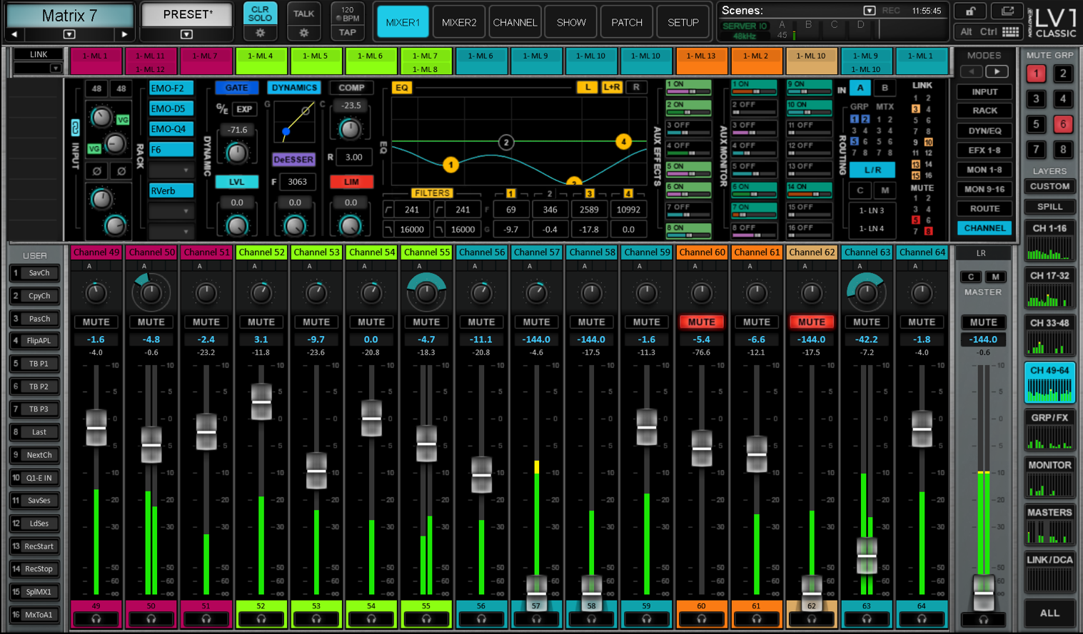
eMotion LV1 Classic’s comprehensive control is built around its large touchscreen interface. The screen, like the LV1 workflow, is organized by windows, pages (tabs), and sections. Windows are the most fundamental level of organization, and each window provides specific processing, routing, or organization. The selected channel name and preset menu are on the left side of the Top Bar. Scene control and system status indicators are on the right. A mouse and keyboard can be added to compliment the touchscreen.
By default, eMotion LV1 Classic opens to the Mixer 1 window. In this view you can adjust preamps, panning, channel gain, select Channel Strip modes, aux sends and routing, and access plugins processing. Other windows are selected with the Top Bar at the top of the window.
Chapter 1: SYSTEM INTERFACE
The Top Bar - Navigating the Interface:
The Top Bar of the eMotion LV1 mixer is a navigation and management tool that is visible from all views. From here you can:
- Access all windows.
- Monitor network and processor status.
- Select a channel.
- Open channel preset and options menus, and control BPM/Tap Tempo.
- Lock the mixer interface.
- Manage sessions and scenes.
- Engage talkback and clear all solos.
- Open the on-screen keyboard and use latching Ctrl/Alt modifiers.
- Open the Mute Groups panel to control the Mute Groups.
- Access User Keys from all windows.
Top Bar Elements

-
Channel NameDisplays the name of the currently selected channel; the box background matches the channel color. The arrows beneath move the selection one channel at a time, and the down arrow opens a drop-down to jump directly to any channel.
-
Channel MenuThe Channel menu is divided into two sections: Channel settings for Presets, Scene operations and Color settings for the selected channel, at the top, and the Session section for saving and loading entire mixer sessions. The menu is always visible from every window.
-
Clear SoloClears active solos or cues on all tracks at once. The gear button below opens the Cue control page to configure cue settings.
-
Talkback (Talk)Engages talkback. The gear button opens the Talkback configuration page where mic source, destination busses, and dim levels are set.
-
BPM / Tap TempoDisplays the system tempo with a flashing indicator. Tap the Tap button in time with the source to establish a tempo; you can also drag on the value or edit it directly.
-
Window Select TabsRadio-button tabs that navigate between the six mixer windows (Mixer 1, Mixer 2, Channel, Show, Patch, Setup). Always present so any window is a single click away.
-
Network Status (SG)Monitors the SoundGrid network and servers. Overview indicators show server-group, I/O, and sample-rate status; a red server-group letter indicates a lost connection or server fault.
-
DSP MetersAverage and peak processing loads for each of the four SoundGrid server groups: green is the running average, the orange line is the peak. A red bar indicates an audio drop.
-
Scenes MenuStores and recalls scenes within the current session. The current scene name is shown; an asterisk (*) follows the name if the scene was modified since recall. Accessible from any window.
-
Record IndicatorA red REC button shows the onboard recorder is recording. Click it to open a menu to start/stop recording and to reach the Media Player.
-
ClockDisplays the console's system time, set in the Admin Configuration kiosk. With MIDI control it can display MIDI time code (MTC) instead.
-
On-Screen KeyboardOpens the on-screen keyboard for when no external keyboard is present. Alt and Ctrl act as locking modifiers; with Alt latched, click a control to set it to its reset value.
-
LockLocks the mixer surface, I/O routing, and/or plugin parameters to prevent unwanted changes during live events. Scope is set in Setup > Mixer Settings > Lock; a password can be assigned.
-
Floating Windows MenuBrings a window to the front and docks all floating tabs and floating plugins. Identified by a double-window icon.
-
Help (LV1 Classic logo)Click the LV1 Classic logo to open an information page showing the version number with links to the user guide and quick-start guide.
-
Tool Bar - User KeysUser Keys 1-16 are available from all windows as part of the Top Bar.
-
Tool Bar - Mute Groups PanelOpens the Mute Groups panel to view status and engage or disengage Mute Groups.
-
Ctrl / Alt ModifiersCtrl and Alt provide alternate actions throughout the mixer and can be used momentarily or latched.
Name
This box displays the name of the selected channel. The list is organized by category (e.g., Channels, Groups, Aux). Use the arrows beneath the channel name to move the channel selection higher or lower, one channel at a time. The down arrow opens a drop-down menu used to access and select any channel directly. The background color of the Name box matches the color of the selected channel.
Channel Menu
The Channel menu (Presets menu) is divided into two sections that serve different purposes. Where needed for convenience, some menu items are multilevel.
At the top is the Channel Presets menu section. Channel presets are snapshots of the current condition of the selected channel. These menu items are used to save, load, export, import, and manage presets. Presets are saved as part of a session. To use presets from another session, select the Import from File menu item. The name of the current channel preset is displayed in the Preset box above. Channel Scene operations such as Recall-Safe and update scenes can also be set here.
Beneath the Channel Presets is the Session section. This provides quick access to sessions and enables you to save the presets for the entire current session as files.
The Channel menu is always visible from all windows.
Menu Item | Description |
|---|---|
Factory Presets (load) | A library of presets supplied by Waves. A factory preset cannot be modified. To make changes, open a factory preset and save as a user preset. |
User Presets (load) | A list of user-defined channel presets saved within the current session or imported from another. To delete a user preset, hold Ctrl before opening the Preset menu. When the User Preset menu opens, preset names will be preceded by a “Delete” option. Select the preset to delete it permanently. This action cannot be undone. |
Import from File | Opens a navigation window to locate presets files that have been saved. Imported presets are added to the User Presets menu. |
Paste | Pastes the copied channel condition to another channel. The Copy command copies all rack information. Paste enables you to choose what channel information will be replaced in the target track. |
Save | Saves the current channel condition to the loaded channel preset, overwriting it. |
Save to User Presets | Creates a new user preset. These are saved as part of the current session. Consider this a Save As function. |
Rename Present | Changes the name of the current channel preset. |
Save to File | Creates a file that is saved in a user-defined location, which can be imported to any session (the extension is .xps). Unlike user presets, these are not embedded in the session. |
Copy | Copies the current channel preset. A copied preset can be pasted to any other channel in the current session. Several Paste options are available. |
Set Channel Color | Enables custom coloring of any channel to improve organization. |
Set Channel Recall Safe | When set, it will excludes all channel parameters from scene changes, even if those parameters are within the scope of the scene change. A small Safe indicator appears next to the channel name when it is in Recall-Safe mode. |
Update Channel in Current Scene | Updates the loaded scene with the selected channel current settings. |
Update Channel in Selected Scenes | The settings of the selected channel will be updated in all selected scenes. Select target scenes in a pop-up window that appears when the menu item is clicked. |
Session Menu Section
This menu section is used to manage presets for the entire current session. It is also used to save and load mixer sessions.
Export User Presets | Creates a file containing all user presets for the entire session, not just those of the selected channel. The exported presets are stored as one .xps file that can be saved to other media. |
Export All Presets | Exports a file that contains the presets—not just the user presets—of all channels in the session. |
Load Session | Presents a list of existing sessions. If the current session has not been saved, you will be prompted to save it before proceeding. |
Load Session Template | Opens a navigation window to load a session template. Loading a template does not alter the current I/O inventory or external patching. |
Save Session | Overwrites the currently loaded session file with the current mixer condition. |
Save Session As | Saves the current mixer condition as a new session. |
Save Session Template | Saves the current session as a session template. |
Sessions and Templates are discussed in the Show chapter of this User Guide.
Set Channel Color
By default, channels are color-coded based on their type (e.g., channels, groups, FX, monitors). You can also assign a custom color to any channel.
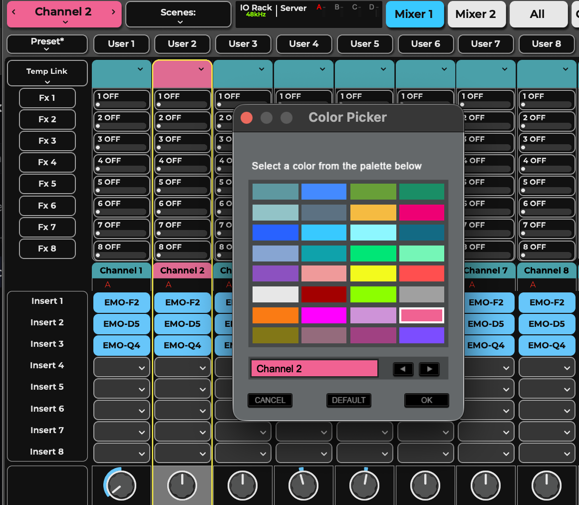
- Select a channel and choose Set Channel Color from the Preset menu.
- The name of the selected channel is shown.
- Select a color. Colors are applied immediately (not upon clicking OK).
- Use the left/right arrows to choose additional channels to customize.
- Click Default to return to the factory channel color. Click OK to exit the window.
You can also assign channel colors from the Patch window. Click the colored button on the color box to the left of a channel name in the rows section to open the Color Picker.
Clear Solo
Clears active solos or cues on all tracks.
Cues and solos are activated in the Mixer window. Configure Cue settings in the Cue control page, which is accessed with the Gear button below Clear Solo. For more information about the cue function, refer to Channel > Cue Section.
Talk
Activates talkback. Click on the Gear button to access the Talkback configuration page. For more details, refer to Channel>Talkback Section.
BPM and Tap Tempo
Displays the system tempo as a value in the box, accompanied by a flashing light. Tap repeatedly on the Tap button to establish a tempo. The taps are averaged to create a steady BPM. You can also click+drag on the BPM number to adjust it or edit the value directly.
Window Select Tabs

Radio button tabs navigate between the six mixer windows.
Mixer 1 and Mixer 2 | Touchscreen fader bank providing extensive control over multiple channels. |
Channel | Provides complete control of a selected channel. This includes channel input, plugins, AUX Monitors and AUX FX sends, output assignments, and assignments such as matrix, linking, delay, and mute groups. |
Show | Manages scenes and sessions and sets recall safe for functions, channels, and busses. |
Patch | Sets patching to, from, and within the mixer. It also configures device connections on the SoundGrid network and sets up delay groups. |
Setup | Establishes overall mixer settings and user preferences. The System Inventory page is where I/O devices and servers are assigned to the mixer. |
Network Status
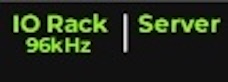
Refer to this panel to monitor the status of the SoundGrid network and servers. The left side displays three overview indicators:
Server | Indicates server assignment. At minimum, one server must be present in Slot A. When the main server is not available for any reason, or is operating at a temperature higher than its limit, SERVER is red. If the main server is operating, but the extra servers are not, SERVER is yellow. |
I/O | Indicates SoundGrid I/O device assignment. This provides the clock and audio throughput. Green indicates at least one I/O is present. Red indicates no I/O device is assigned to the system. |
Sample Rate | Displays system sample rate. |
Reports network status. Messages may indicate a sample rate mismatch, a general change in network status, a buffer overload, etc. Troubleshoot network and device issues in the System Inventory page (Setup > System Inventory).
DSP Meters
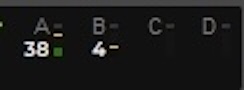
A server group consists of one active server and possibly a redundant server. There are four server groups. Each server group has a meter bar that displays the average and peak processing loads of the active server. The group’s average processing load is displayed as a green bar and its peak as an orange line.
Red indicates that an audio drop has occurred. This may happen for two reasons:
Processing overload (momentary or constant) Solution: Disable some plugins
Some plugins exhibit a high average/peak ratio. This may cause temporary CPU overloads that result in audio drops. When adding many of these plugins, the peak and average indicators will drift apart. In such cases, some of these plugins may need to be disabled.
Network connection errors (channels over the network) Possible solution: Increase server network buffer size.
A red server group letter indicates a lost server connection or a server fault. The mixer can still be used in an offline mode with offline devices assigned in the inventory.
Go to Setup > System Inventory to investigate network problems.
Scenes
The Scenes menu is used to quickly store and recall scenes within the current session. The name of the current scene is displayed in the box. If a scene has been modified since it was recalled, it is followed by an asterisk (*). The Scenes menu is accessible from any window.
Store New | Creates a new user-named scene based on the current condition. |
Store | Overwrites the recalled scene with the current mixer condition. |
Recall Scene | Directly recalls a scene based on its place in the scenes list. Type a number and the corresponding scene will be recalled. |
Hot Scenes | Provides immediate access to up to eight high-priority Hot scene snapshots. |
Scene 1–32 (scene select submenu) | Shows all scenes associated with the session in banks of 32 scenes (maximum number of scenes: 1000). |
Record
A red REC button indicates that the onboard recorder is in record. Click the REC button to open a drop-down menu to start and stop record and to access the Media Player.
Clock
Displays the console’s system time. Set the time in the Admin Configuration kiosk. When MIDI control is used, this box can display MIDI time code.
On-Screen Keyboard
Click the keyboard icon to open the on-screen keyboard, which is useful when no external keyboard is available. Alt and Ctrl act as locking modifiers. When Alt is selected, click on a control to set it to its reset value.
Lock
Locks or unlocks the mixer surface, I/O routing, and/or plugin parameters to prevent unwanted changes during live events. The scope of the mixer lock is defined in the Setup window (Setup > Mixer Settings > Lock). A password can be assigned to this function
Floating Windows Menu
Brings a window to the front and docks all floating tabs and floating plugins. This menu is identified by a double window icon.
Help
Takes you to an information page displaying the eMotion LV1 Classic version number and provides links to the user guide and the quick start guide.
User Keys

Many mixer actions can be assigned to sixteen keys in the Mixer window. Clicking on a key will trigger its corresponding action. Common assignments include loading and saving sessions and scenes, navigating between channels and views, and controlling channels and plugins. The name of an action is indicated on its assigned key.
User-assignable keys are assigned in the U/I Settings page. (Setup > U/I Settings > User-Assignable Keys). They are recalled from the left side of the touchscreen Mixer window (shown here on the left).
To trigger user-assignable keys from the fader bank, set the User Keys/Ch Select button to “User Keys.” The scribble strip of each channel will display a user key name. Click the Channel Select button that displays the desired key name.
Mute Groups Panel

Mute group assignments are made in the Output Section of the Channel Focus and Main Route modes, in the Channel window, and in the Patch window. Refer to Channel > Output Section > Main Outs Assignment Panel.
Mute groups are activated in the dedicated collapsible panel on the Top Bar.
All member channels of an activated mute group display a flashing Mute button.
Any member of an active mute group can be unmuted by clicking its Mute button. Clicking it again mutes the channel beyond the scope of the mute group. It will remain muted even after the mute group is deactivated.
A third click returns the channel mute to normal mute group behavior.
Ctrl / Alt Modifiers
Ctrl and Alt modifiers provide alternate actions throughout the mixer. They can be used momentarily or latched from the on-screen keyboard.
Floating Windows
Many of the software interfaces can be undocked from their original locations, as floating windows and then moved to another display. This applies to the main windows, control panels, plugin interfaces and settings panels.
Floating Main Window Select Tabs
Each one of the main windows can be detached from the original screen to use on other displays.
Original view: All tabs are available.

To create a secondary view, click/drag its tab downward, away from the Top Bar. The new floating window will appear on a secondary display.

This new secondary display will show the selected window only.

The main display can access all windows except the secondary view. To return to the complete view, close the floating windows.
Floating Device Control Panels
The control panel for any I/O device, driver, server, or controller opens as a floating window. You can open a device control panel from the System Inventory page it will already be flaoted and can be moved to any available display.
Floating Plugin User Interfaces
Floating a plugin user interface window starts by un-docking it from its Rack, this can be selected in the Rack menu or Click on a plugin icon in a rack to open its user interface, than Click the Expand button in the upper-right corner to undock the interface into a floating window.
When another plugin is undocked, the current plugin window will automatically be redocked. Pin a plugin window to keep it undocked. Floating plugin windows are set to remain “always on top” in relation to the main application windows.
Flaoting plugin layout - location and size can be saved in session and in scene. Up to five plugin windows can have their layouts changed with a scene change.
Floating Routing View Panel
Access the Undock Routing View panel In Setup > System Inventory to monitor network activity continuously.
Floating Windows Management Menu
This menu provides a list of all current floating tabs (e.g., Channel, Patch, Routing Panel) and floating plugin user interface windows. It’s a quick way to keep track of your floating windows and to find those that may be hidden beneath other windows. Click on a window to bring it to the front.
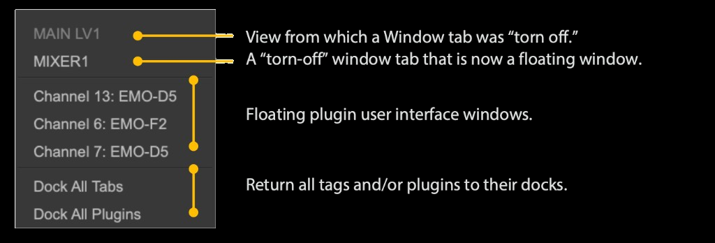
View from which a Window tab was “detached.” A detached window tab that is now a floating window.
Floating plugin user interface windows.
Return all tabs and/or plugins to their docks.
Floating windows configurations are part of a scene and will normally change when a scene is recalled. You can, however, choose to make floating windows recall safe or outside the scope of a scene change.
Set Scope and Recall Safe in the Show window.
Precision Control
You can increase a control’s resolution (that is, slow down the control) by holding the Control key while dragging. This applies to long faders, aux faders, preamp gain, channel trim, and pan. Release Control to return to regular resolution.
To return a control to its default position, hold Option and touch the control.
Console Updates
To ensure optimal performance, keep your eMotion LV1 Classic up to date. When a software update is available, you will receive a notification from Waves. You can also visit waves.com to see if updates are available. An internet connection is required for software updates.
To check for updates and to update eMotion LV1 Classic software, follow these steps:
- Open the Admin kiosk from the button on the left side of the Setup window. This will quit the console.
- In the Admin kiosk, open Waves Central and log in using your Waves credentials. In Waves Central, click Updates Available to update LV1 and any other Waves products for which updates are available.
- To install specific plugins or plugin bundles, select All Plugins at the top of the page and choose from the list. Note that certain plugin bundles cannot be installed on Classic from Waves Central.
- In some updates, firmware updates may be required for I/O devices or servers, these are performed only after Waves Central update part was completed and LV1 is back up. Go to the Setup page, When the FW button on a device icon in the System Inventory is light up, click it and follow steps to update the device.
- You may need to restart the console after updates.
For detailed instructions, refer to this technical article on updating the console.
Admin Kiosk Interface
The Admin kiosk is used for maintenance, troubleshooting, file access, system recovery, and accessing the media player. It can be accessed from any page in the Setup window.
In Setup window, pressing Admin quits LV1 and opens the Admin kiosk. You can reopen LV1 from the kiosk. Going to the Admin kiosk takes you out of the console. Your session information will be saved, and it will be restored when you click “LV1.”
The Admin kiosk is organized into two view modes: Basic and Advanced.
To set the time and date, use the pencil on the top-right side. This is important, for internet connection and console updates.
Basic Admin Kiosk Panel
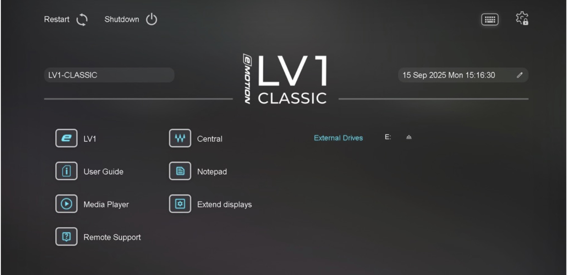
-
LV1Relaunches the console.
-
User GuideOpens a PDF user guide that you can read on a browser or PDF viewer.
-
Media PlayerOpens a media browser that enables playback through the console. The source can be a local file or a streaming service. This is commonly used for “walk on” music before an event begins. Patch the driver to an LV1 input channel.
-
Remote SupportOpens a utility that enables Waves technical support to troubleshoot your LV1 remotely.
-
CentralTakes you to Waves Central, the application for installing Waves software and licenses. Check in with Waves Central regularly for software updates.
-
NotepadProvides a space to create notes.
-
Extend DisplaysTakes you to the display configuration control panel.
-
RestartShuts down and relaunches the console.
-
Shut DownCompletely shuts down the console.
-
KeyboardOpens an on-screen keyboard.
-
AdvancedOpens advanced ADMIN panel
-
External DrivesDisplays all external USB drives connected to the system. Use this to eject removable media. Do not remove an external drive without first ejecting it, as this may damage the drive and compromise the data on it.
Advanced Admin Kiosk Panel
Click the gear icon on the right to enter the advanced admin mode. You will receive an “Are You Sure?” confirmation prompt. The Advanced controls are on the right. There are four tabs.
The name of this system is shown in a box on the left side. This is useful when several LV1 systems are members of a SoundGrid network.
To change the System name, click the pencil icon at the top-left side, avaibale on Admin mode.
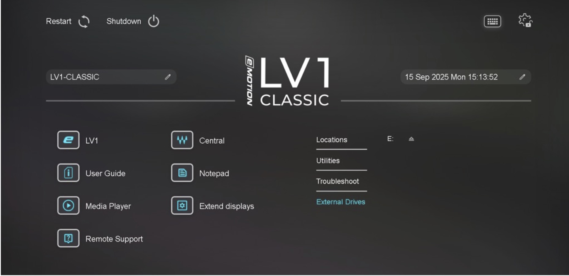
-
Locations
-
Utilities
-
Troubleshoot
-
External Drives
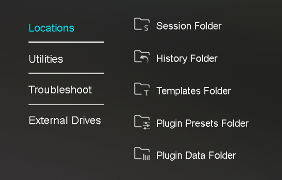
Locations takes you to the default folders where your LV1 files are stored. Open these folders to delete or copy session information.
Utilities consists of four functions:
(1) Browser takes you to the internet browser.
(2) Fader Bank Service provides a firmware update and/or fader calibration. Full restart required.
(3) rtpMIDI is the bridge that lets Classic interact with MIDI. When rtpMIDI is installed, the indicator is lit.
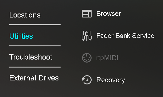
(4) Recovery returns the console to factory settings from a disk image built on your current software version. This will not affect your saved files (sessions, templates, history, plugin presets, and plugin data).
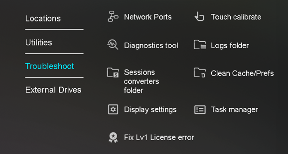
Troubleshoot provides maintenance and service utilities. Some are intended for skilled users and administrators, while others are used when troubleshooting with Waves technical support.
Troubleshoot Options
Network Ports | Opens the Windows Network Connections panel. The Network connection is usually the internet connection. The SoundGrid network connects all internal Classic components as well as external devices. |
Diagnostics Tool | Waves technical support may request a comprehensive assessment of your Waves system. This procedure scans the relevant sections of the console’s computer. |
Sessions Converters Folder | Sessions converters enable you to preserve a session when the software version changes. Normally this is transparent, but if you have a problem loading a session after a software update, check that the version of the session converter matches the version of the eMotion LV1 Classic software. If necessary, load the correct session converter from Waves Central. |
Display settings | Opens the Windows Display control panel. |
Fix LV1 license error | If LV1 Classic does not load, the kiosk will open and there will be a message regarding the license. To resolve the issue, select Advanced Admin options/Troubleshooting and choose “Fix LV1 License Error.” This resyncs the license with the Classic console that you are using, regardless of who operates or owns it. If, for example, you encounter a license error on an LV1 Classic that you rented, you can connect the console to the internet, resync the license, and continue working without logging in to Waves Central. This requires an internet connection. |
Touch Calibrate | Opens the Windows touch-screen calibration tool, used to coordinate touch controls on two or more displays. This is needed only when using an additional external display. |
Logs Folder | A list of all technical logs. This is used primarily when consulting Waves technical support. |
Clean Cache/Prefs | Clear these folders when you encounter unusual issues when instantiating plugins (such as loading old plugin versions or taking longer than expected to load). Clearing the preferences will require you to reset certain configurations. |
Task Manager | Opens the Windows Task Manager. |
Reset Network Ports | Use if the Network port in the System Inventory page is not properly reporting or cannot find the right port. |
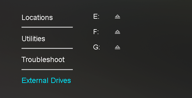
External Drives is a file browser that lets you access your connected drives.
Chapter 2: MIXER WINDOW
The Mixer window is inspired by traditional mixing consoles, making it the most familiar view for many operators. It provides a broad, multichannel overview of the mixer, including inputs, routing, plugins, assignments, and channel parameters. Parameters controlled in the Mixer window can be accessed and expanded in additional LV1 windows, such as the Channel window or Patch window.
Mixer Window Overview
The Mixer window provides comprehensive control over channel and mix parameters, from basic fader and pan controls to assignments, channel processing, automixing, and immersive panning. Each Mixer window can display up to 16 channels plus one master channel, and Channel Layers let you populate the mixer with different input and mix channels. The mixer is organized into four main sections.
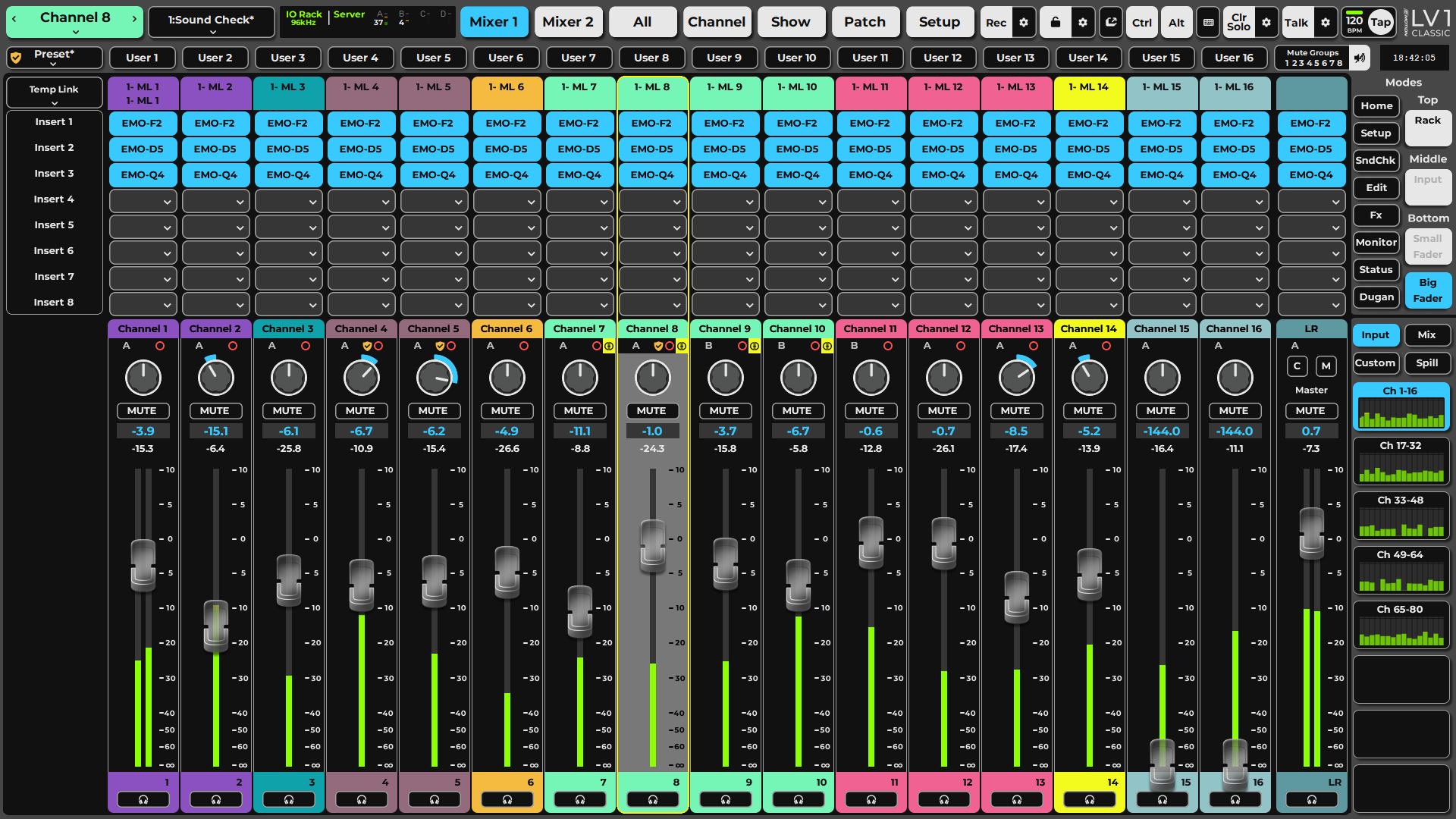
-
Mixer ChannelsChannels consist of channel strips that control individual channels, and Channel Strip modes that define how a channel or buss is controlled and viewed.
-
Master FaderThe master fader controls the overall output level. In the sends on faders mode, it controls the output level of the aux channel.
-
Mixer Modes - Top / Middle / Bottom settings and PresetsMixer modes provides overeview of differnt paraemters accross the populted layer channel strips. For example Input prameters or Rack settingSet the Mixer mode for the Top, Middle or Bottom rows, use the Big Fader button to override the Middle and Bottom setting. Use Presets to set the layout for all the rows at once. Presets can be saved and renmaed in the mode setting menu in each white Mode cell
-
Mixer LayersMixer layers determine what populates different mixer channels—what is being viewed and controlled.
Mixer Channel Strips
On Screen Channel Strip
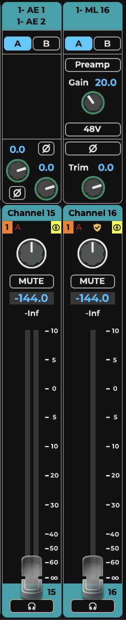
-
Channel Strip Input sectionChannel Input assignment display and assignmnet menu. Chanell configuration can be set here as well as specific input functions per channel type.
-
Mixer Modes sectionMixer Modes provides control over many of the channel parameters, group by functions or processing features. There are 3 Mixer modes sections located at the top of the channel strip, the middle and the bottom. Input mode is displayed in the image.
-
Channel Name and indicatorsChannel Name and color are displayed double click/tap to edit name, Tab to save name and open next channel name for edit. The indicator section displays the active Link group number for an assigned channel, Recall Safe, Processing Server assignment, Record arm/active, Dugan active/group for compatible channels, and Post FX state for Groups.
-
PannerThe Panner is using a -3dB law for panning mono to stero, and a Balance mode for stereo channels and mix busses, in addition to its value it displays a semi ring indicating its position. Using CTRLand Pan for stereo channels controls the Width parameter. More panning options are available in channel window. When in SOF Flip teh displayed panner is for the send, and may change to an IEM 360 panner.
-
MuteActivates channel Mute that cuts the channels's outputs to all its post fader recipients, and pre fader recipients as set in the Mixer settings. When a Mute is set from a Mute group, a DCA or Solo mode, it will flash. Pressing Mute while it flashes makes a hard mute, pressing again temporary releases the mute
-
Fader value and Meter valueFader value (dBFS) is displayed by default, and Panner values (Pan Degrees, Width scale) are displayed when panning.
-
MeterDisplays Input or Output peak beam and a numerical value. Meters range from -144 to +10 dBFS.
-
FaderControls the channel Output gain by default, ranging from -144.0 to +10.0 dBFS. When in SOF Flipit will control the send level for theAux destination. When inInput mode (for set Aux tracks) it will control the input gain (Trim).
-
Cue / SoloActivates Cue send by default. Can be set to SOLO mode for Input/Group channels. The channel/mix type index and teh assigned color is displayed next to the Cue.
Tactile Channel Strip

-
SelectSelects the channel by default and activates a user key when is set to User key mode. The select button color will reflect the corresponding channel color.
-
Channel Scribble DisplayDisplays the channel strip info, channel Name, Rotary control label and value, Rotary push label and value, and user key name when in User Key mode. Mono/Stereo Meters are displayed on the right of the Display, ranging -144 to+10 dBFS.
-
Rotary EncoderThe channel strip rotary encoder function is set by dedicated controls on the fader bank, by default its set to Pan mode. When in Gain mode it will control teh channel input Gain or Trim, when in Edit mode it will control the Channel parameters or Plugin parameters when selected,
-
Solo / MuteActivate Cue/Solo or Mute for the channel strip reflecting the state as set from teh screen or remote.
-
Motrized FaderChannel strip Fader controls the channel output by default, when in SOF Flip it will control the send level, and when set to input mode it will control an aux input. Fader range from -144 to+10 dBFS. As the faders are motorized they will change their position when changing layers or Flip modes. The Fader senses touch in order to avoid moving by unwated objects.
Mixer 1 window is, by default, linked to the LV1 Classic fader bank and can be controlled from the tactile surface in addition to the touchscreen, providing quick access of multiple channels.
Channel Strip Elements
The channel strips on the touchscreen and the fader bank are functionally identical, although some controls, by necessity, are presented differently. Fader bank channel strips are mapped to the touchscreen interface. They use the same logic and flow as the touchscreen channel strips.
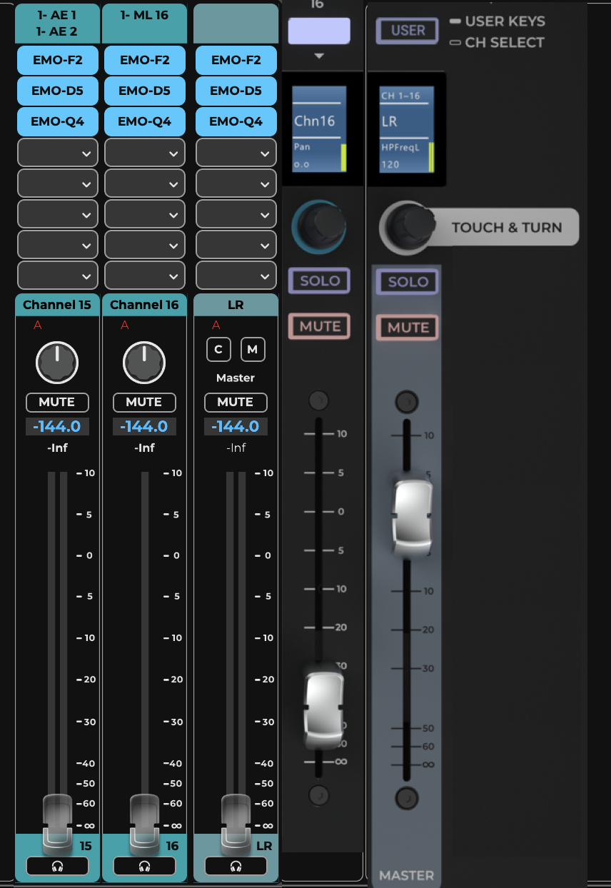
Function | Fader Bank | Touchscreen |
|---|---|---|
Channel Select | Select Channel on the Select button and choose a channel or touch a fader. | Touch the fader or the lower section of the channel strip. |
Pan | Turn the encoder knob when the encoder panel is set to Pan. | Panner controls panning and on Aux busses, it may control immersive monitoring. |
Input Gain | Select “Gain” on the Encoder selector. In this mode, preamp gain or trim is controlled. | Can be set in Input or Channel Focus modes . Controls preamp gain or trim. |
Scribble strip | Multipurpose display that changes by function: Channel Name, User Key function, encoder parameters labels and values | The Channel Name box is akin to the scribble display |
Fader | 100mm ALPS fader mapped to touchscreen fader. | High-resolution. -144 dB to +10 dB |
Solo/Mute | Solo and Mute buttons are in the middle of the channel strip. A mute activated by the user for a specific channel will be solid red; a mute activated by a mute group or solo will flash when a Mute button on channel is flashing. | Solo/cue button is at the bottom of the channel strip. Mute is in the middle. A mute group is activated on the touchscreen. |
Channel Meters | Inside the scribble strip. | Under the faders. |
Master Fader
The master fader controls the overall output level. Like the channel strip faders, it includes a fader, meter, mute, and cue. When sends-on-faders is used, the master fader controls the Aux channel fader.
The Master fader on the fader bank follows the Master Fader in the touchscreen. Its meter is displayed in the scribble strip. The Master fader can be mapped to any channel if required. Mastre fader does not change when changing layers, howeevr it will flip to Aux master in Aux SOF Flip mode.
Touch Screen Master Fader

-
Master Channel Strip Input sectionWhen a Master channel strip is mapping an Aux buss or other specific Channel, Input assignment menu can be acessed here. Channel configuration can be set here as well as specific input functions per channel type.
-
Mixer Modes sectionMixer Modes provides control over many of the channel parameters, group by functions or processing features. There are 3 Mixer modes sections located at the top of the channel strip, the middle and the bottom. Input mode is displayed in the image.
-
Channel Name and indicatorsChannel Name and color are displayed double click/tap to edit name, Tab to save name and open next channel name for edit. The indicator section displays the active Link group number for an assigned channel, Recall Safe, Processing Server assignment, Record arm/active, Dugan active/group for compatible channels, and Post FX state for Groups.
-
Master selectWhen in Big Fader mode for the Main Master, a quick toggle to Center and Mono masters is available.When the Master Channel stripis set to another type of channel this section will populate a panner.
-
MuteActivates channel Mute that cuts the channels's outputs to all its post fader recipients, and pre fader recipients as set in the Mixer settings. When a Mute is set from a Mute group, a DCA or Solo mode, it will flash. Pressing Mute while it flashes makes a hard mute, pressing again temporary releases the mute
-
Fader value and Meter valueFader value (dBFS) is displayed by default, and Panner values (Pan Degrees, Width scale) are displayed when panning.
-
MeterDisplays Input or Output peak beam and a numerical value. Meters range from -144 to +10 dBFS.
-
FaderControls the channel Output gain by default, ranging from -144.0 to +10.0 dBFS. When in SOF Flipit will control the send level for theAux destination. When inInput mode (for set Aux tracks) it will control the input gain (Trim).
-
Cue / SoloActivates Cue send by default. Can be set to SOLO mode for Input/Group channels. The channel/mix type index and teh assigned color is displayed next to the Cue.
Fader Bank Master Fader
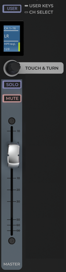
-
User Keys / Ch Select toggleChannel Select/User Keys toggle that sets the function of the button at the top of each channel. To trigger user-assignable keys from the fader bank, set it to User Keys.
-
Scribble stripDisplays the master fader meter on the fader bank; its meter is shown in the scribble strip.
-
Touch & TurnQuickly map this knob to one control for instant access.
-
SOLOSolo control for the master fader on the fader bank; the fader bank Master Fader matches the touchscreen Master Fader, which includes cue/solo and mute.
-
MUTEMutes the master output. The fader bank Master Fader is the same as the touchscreen Master Fader, which includes a mute.
-
FaderFader bank master fader. It controls the touchscreen Master Fader and is the same except for layout and certain fader bank specific functions.
Mixer Modes
Channel Strip modes determine the processing, routing, and views for all channels in a layer. Modes are displayed in the large section in the middle of the mixer. They are selected via the panel on the right (highlighted in the yellow circle here). Toggle between the selector pages using the arrows above the panel.










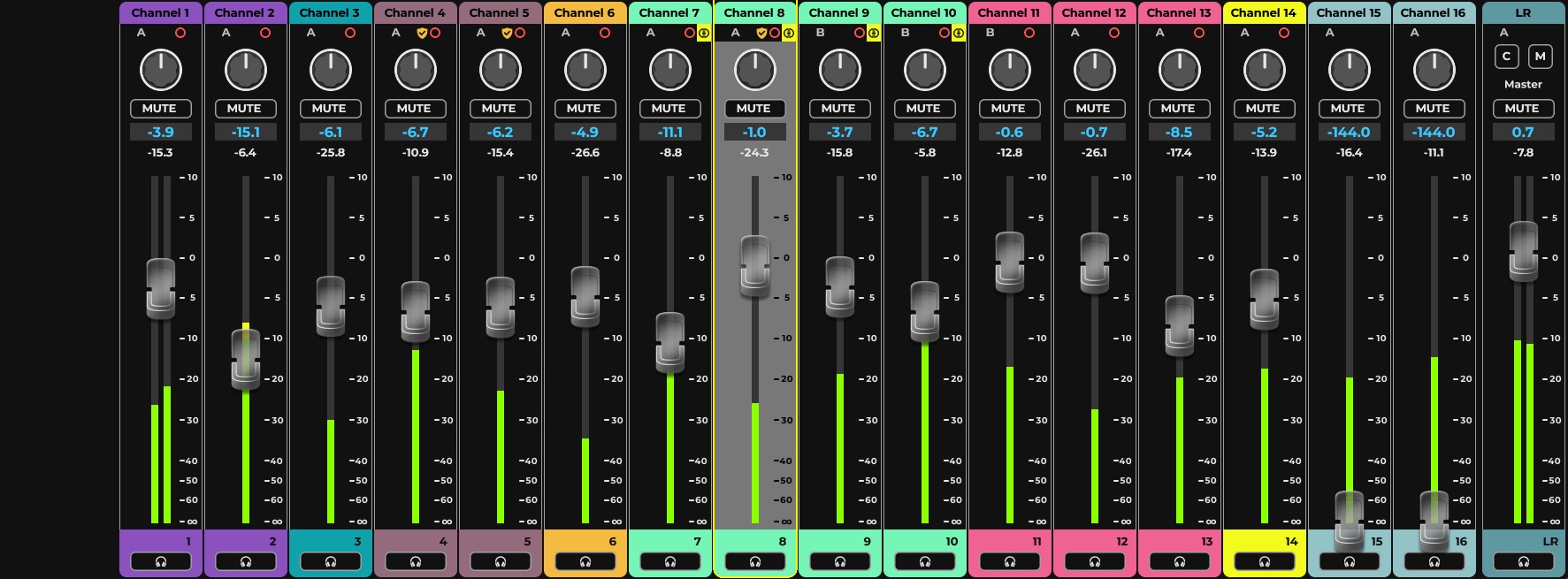
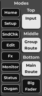
-
Mode Selector (Top / Middle / Bottom)The Top, Middle, and Bottom selector positions display the currently active modes (e.g. Input, Group Route, Main Route, Big Fader). presseh selector button will option the Mode options menu. The Mode option menu is userd to save new layout for the presets and to rename them.
-
Big Fader ModeBig Fader mode overrides the Middele and Bottom mode layouts.
Mixer Layers
Mixer Layers populates the channels strips with different channels. There are several banks of mixer layers, each comprises 8 layers, the default Factory banks, Custom layers bank and Spill layers bank. Mixer Layers can be selected from the touch surface or the fader bank.
When a large Channel mode is enabled, the factory channel layers bank will be split to two banks, INPUT and MIX. INPUT will map all the input channels available, MIX will map all the available busses and outputs. The MIX layer has its own color (deep blue), while Input uses the original factory color (light blue).
Touch Screen Layer Select
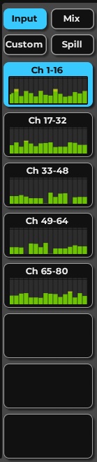
-
Layer Bank SelectorMixer Layer Bank options, Factory - for small configurations, Input - large configurations Input channels, Mix - large configurations Mix Busses (Groups, Auxes, Matrix, Main, DCAs). Custom - for user customized layers layout. Spill - for selected DCA members layers
-
Layers ButtonsEach of the 8 layers can populate up to 16 channel strips, each is represented with a meter (active or idle). Each layer has its dedicated name. Layer name can be edited in Custom Bank. Each Bank will highlight the selected layer with a different color, light blue for Input, dark blue for Mix, purple for Custome, and yellow for Spill.
Fader Bank Layer Select
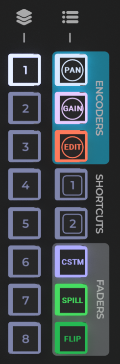
-
Mixer Layer ButtonsThe Mixer Layer Buttons select a layer from the active bank, by defualt the Factory Layer Bank. The button backlight and selected light indicates the selected bank in coherece with the Touchscreen buttons colors.
-
Custom Layer ButtonSelects Custom Layers bank.
-
Spill Layers ButtonSelects Spill mode and its Layer bank for the selected DCA group members
-
Shortcuts ButtonsCan be assigne to selected functions,such as Input / MixBank toggle.
Mixer Modes
The Mixer windows comprised from channel strip population and Mixer Mode controls and info. Selecting layers changes the channel strips that are being displayed and controlled, while modes offer variable views and control for each strip.
Mixer Window Layout
There are two layouts that can be set, a three Mode rows layout, and a single Mode row with the Big Fader. While the three mode layout provides comprehensive control and info, the Big fader based layout is more foused and is easier for mixing using the touch screen or a remote tablet.
Around these rows, at the very top there is a short row for the Input section of each channel strip, this section may have a pull down menu with input assignment options and operations. Just above the middle row, there is a section dedicted fro channel names and important indicators for Link status, processing server assignment, recall safe, recording, Dugan enabled channels and post effect groups. At the bottom of the mixer window there is access to the channel strip Solo/Cue and indications of the type and index of the strip.
The Mixer Mode selectors are located at the top right side of the Mixer window, while the Layer Banks are located at the bottom right.
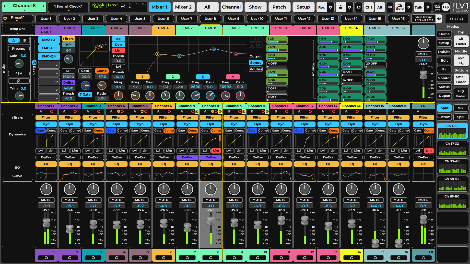
-
Top Mode - Row 1Selected by the corresponding square menu or by Mode preset.
-
Middle Mode - Row 2Selected by the corresponding square menu or by Mode preset. Will be overridden in Big Fader mode.
-
Bottom Mode - Row 3Selected by the corresponding square menu or by Mode preset. Will be overridden in Big Fader mode.
-
Input SectionDisplay the channel input assignment for Input Channel type, and provide input options and operations for other channel types.
-
Name and Indications SectionDisplays channel Name. Edit Channel name by double tapping, edit next channel by clicking Tab on the keyboard, save name by clicking Enter on the keyboard.
-
Solo / Cue sectionOperate Solo or Cue and displays the Channel strip type and index.
-
Mixer Mode Selectors
-
Mixer Layer Banks
Mixer Modes Selectors
The Mixer Modes selector section comprises per row mode selection menu, a Big Fader mode toggle and 8 mode layout presets.
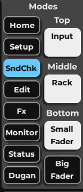
-
Mode PresetsThe 8 Mode Layout Presets provide quick access to custom layers of information per channel strip. While these are factory set, they can be modified and renamed by the user from the Top/Mid/Bottom Menus.
-
Top Mode MenuSelect the Mode for the Top row, the selected mode will be displayed in the box. Top mode is always avaible and can be set by an assigned user key.
-
Middle and Bottom Mode MenusSelect the Mode for the Middle and Bottom rows, the seelcted mode is displayed in the box. The Middle and Bottom rows will be disabled when Big Fader mode is enabled.
-
Big Fader ModeWhen activated Big Fader mode overrides the middle and bottom mode rows, displaying a large fader section with a large meter. This mode is useful for Touchscreen and Tablet operation, when no tactile faders are at reach.
-
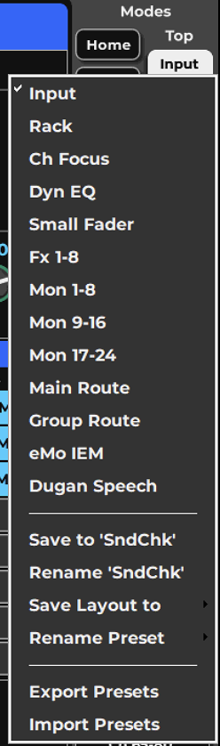
Select ModeAll available Modes are listed here and can be selected to populate the Top/Middle/Bottom rows. Mode options may change with Mixer configurations selected or with feature license availability
-
Save / Rename CurrentSave and Rename the Current selected Mode Layout Preset
-
Save / Rename PresetSave and Rename a selected Mode Layout Preset
-
Export / Import PresetsExport Presets to another session or system, or Import previously exported presets from file.
Input Layer Mode
The Input Channel Strip mode manages signals from I/O devices or internal busses. In this mode, each layer includes digital trim controls and pan/balance/rotation controls for each channel or buss. When a channel is patched to an I/O with a preamp, the Input Mode provides control over the preamp.
Input and Preamp Controls

- Controls Available on Channels With or Without a Preamp If there is no preamp on the channel, only the A/B Input selector, Trim, and Phase reverse are available.
- Preamp Analog Gain Control: Adjusts the analog level of an I/O device preamp. Knob position is displayed in the value box and with a blue ring around the knob. Stereo channels have independent L/R input controls or they can be linked. This is set in the which are set in the Channel window. Preamp control range varies depending on the I/O, and adjustments made in the I/O control panel are reflected here.
- Preamp/Local Select (click the Preamp button to toggle) Preamp mode adjusts the preamp’s analog gain, just like the preamp gain control in the device’s control panel. Local is a digital gain stage that always delivers the user’s requested input gain, regardless of the preamp’s analog gain setting. Refer to refer to Channel >Input Sections >.
- 48V Phantom Power: Activates the microphone preamp 48V phantom power. Stereo channels have independent L/R 48v phantom controls. Options: On/Off; default: Off
- Input Selector lets you choose between mixer inputs A or B.
- Channel Trim: Trims channel input level digitally. Stereo channels/busses have independent left and right trim controls that can be linked. Range: -144 dB to +10 dB
- Input Polarity Reverse: Reverses the polarity of an input channel. Each channel of a stereo input can be controlled separately. Note that the location of the polarity and 48V differ between mono and stereo channels. Options: On/Off; default: Off
- Additional Controls Available on Channel Window When a Preamp Is Present
To Control Input Gain from teh Fader Bank, Use a channel’s encoder knob to control the preamp and adjust channel trim. When the encoder knobs are set to control gain, they automatically map to the channel input’s preamp-Gain or local-VGain. If there is no preamp, the encoder knobs control the channel trim. Gain value is shown in the scribble strip.
Dynamics/EQ Mode

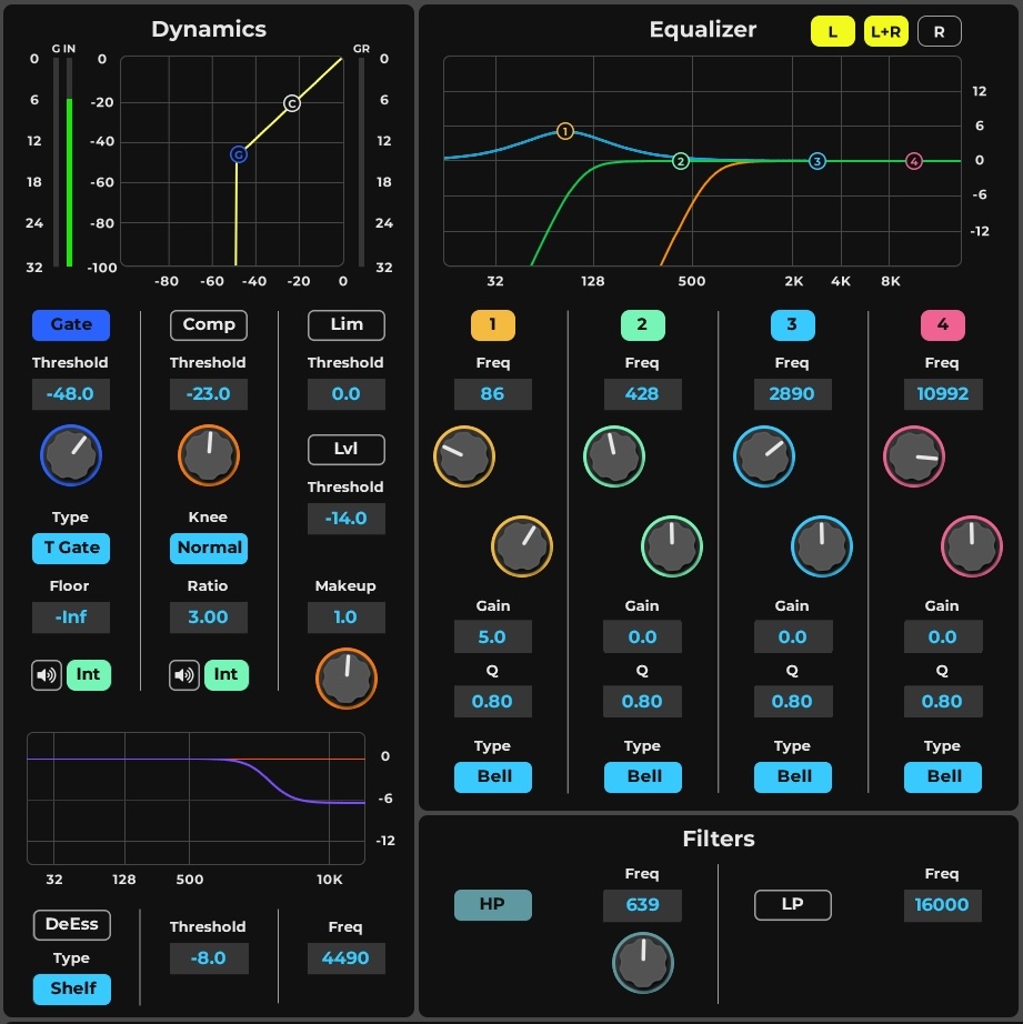
The DYN/EQ mode displays the controls and graphics of plugins that have been assigned to Main Channel processing. It provides a single-page overview of the dynamics, EQ, and filter processing for an entire 16-channel layer.
Each channel’s mode section includes graphic displays of specific EQ and dynamics processors. Plugins can be bypassed with the display buttons. A selected plugin or section is bypassed when its indicator light is off.
Filters, EQ, and Dynamics buttons turn their respective processing sections on or off for the entire plugin. In addition, the specific dynamics sections (gate, compressor, leveler, limiter, de-esser) can each be bypassed. For further control of a plugin, click on its graphic display to open the plugin user interface in the Channel window.
-
EQ and Filters sectionEQ and Filter processing in Channel Window Main Control section. The Filters and EQ buttons turn their processing sections on or off, and clicking the graphic opens the plugin interface in the Channel window. By default mapped to eMo-Q4 and eMo-F2.
-
DynamicsDynamics Processor in Channel Window Main Control section. Dynamics section provide control over Gate, Compressor, Leveler, Limiter and DeEsser. By default mapped to eMo-D5.
Rack Mode

The Rack mode displays the plugins and external inserts for channels in the current layer. It provides an overview of the processors on each channel or mixer buss. In the Rack mode you can move and copy plugins between racks, re-sequence rack order, and bypass, disable, and remove plugins from racks.
Each channel rack can hold up to eight plugins.
Click on a plugin icon to open its user interface in the Chanenl Window or select to Float the plugin interface from the menu.
Inserting a Plugin
To add a plugin to a rack, click the small arrow on an empty rack slot, or click+hold on the slot itself. This opens the Plugin menu. Search for a plugin or go to the Plugin List sub-menu and choose from among the available plugins. Its name then appears in the rack slot. Click on the icon to access the plugin user interface.
The Plugin menu is also used to manage presets, copy parameters between plugins, and to monitor channel latency. These functions are described in detail in the Channel Window chapter of this manual (Channel>Rack Section>Adding and Managing Plugins).
Certain regularly used Plugin menu items are described in the next section of this manual.
Managing Plugins From the Rack
Bypass
Bypasses the plugin while keeping it in the processing chain. A bypassed plugin appears with a white background in the rack. Bypass from the Menu or by clicking alt+Ctrl+plugin name.
Disable Plugin
Removes the plugin from the processing chain without deleting it from the rack. Disabling plugins that are currently unused may reduce rack latency. Higher rack latency can result in an accumulated delay from the buss inputs. You can re-enable the plugin without losing its settings, controls, or automation assignments. When a plugin is disabled, its name will remain visible, but the slot will appear as black. Disable from the Menu or by Ctrl+click on plugin name.
Remove Plugin
Deletes the plugin from the slot. All parameter settings and control assignments are lost. Remove from the Menu option or by dragging the plugin out of the rack.
Adding and Deleting a Row of Plugins
Hold the Alt key while selecting Insert or Remove from the Plugins menu to extend the action across an entire row, throughout all channels in the session. The on-screen keyboard provides latching Alt and Ctrl modifier keys
Latency
Menu Latency indications for:
Latency Compesation On/Off - Removes the plugin from plugin/buss latency compensation calculations. The plugin remains active, but its latency is no longer reported to the delay compensation engine. This prevents a plugin with a particularly long delay from delaying the entire buss.
Latency - indicates the plugin latency.
Rack Latency - indicates teh accumilated latency of all plugins and routing.
Organizing Plugins in the Rack Channel Strip Mode
Rack signal flow is from top to bottom of the rack. Some plugins are designed to work together in parallel without regard for processing sequence. With these plugins, rack order is unimportant. Refer to the plugin’s user guide for details.
Moving, copying, and controlling the plugin icons is executed on the touchscreen. Take caution to avoid inadvertently touching an icon and changing its condition.
Controlling Plugins From the Rack Single click: Opens the user interface of the plugin or external insert.
Single click + hold: Opens the Plugin menu.
Ctrl + Alt + click: Bypasses the plugin.
Ctrl + click: Disables and removes the plugin from the DSP processor.
Drag an icon off the left side of screen: Removes the plugin permanently.
Moving and copying plugins using their icons
Click + drag icon: Moves a plugin and its presets to another rack slot.
Alt + click + drag icon: Copies a plugin from one rack slot to another.
Drag a plugin to change its position in the rack. Drag to move a plugin or external insert to another channel or use Alt+drag to copy. Latching Alt and Ctrl keys are located on the on-screen keyboard. Move a mono plugin module to a stereo channel and the plugin becomes a stereo module. The mono plugin’s parameters will be applied to both sides of the stereo module. If a stereo plugin is moved to a mono channel, then settings of the left stereo channel become the mono parameters.
Do not add, remove, disable, or move a plugin when an audio dropout is not acceptable. These actions change the structure of the plugin rack, which can result in a brief interruption. Bypassing a plugin or changing its parameters can be done at any time.
Route Modes
Use the Route modes to patch within the mixer and to I/O devices. Route Modes provides an overview of the internal and external patching in the mixer view.
Main Route

Main Route Mode is used to overview and set assignmnets for the internal Main Mixes, the Matrices and Mute groups. Its also used for assigning a channel for internal Record (when avaiable). IO outputs can also be assigned from here, displaying the last assignment made. For stereo outputs assign pairs or use Ctrl+click to assign individual IOs per side.
Group Route

Group Route Mode is used to inetrnally assign channels to Processing Groups, and to Link / DCA groups.
Aux Sends Modes

In the large LV1 configurations Aux Busses are devided to FX and Monitor busses for routing simplicity. FX busses are used primarily for effects processing. As FX preceeds Monitors in the processing signal flow, they can be sent to MON busses and to the main mix. Mon busses can be sent directly to an I/O. All Aux busses can be sent to each other providing the destination is a higher index Aux buss. Aux Sends Modes are split to groups of 8 and provide a quick Sends-On-Faders Flip option.
Controlling Aux Sends Cells
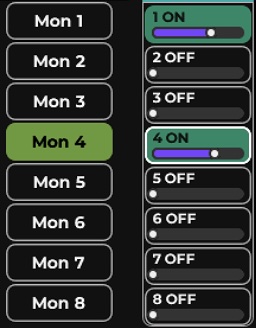
- Select an AUX Mode (e.g., MON 1–8)
- Turn an aux send on or off by double-clicking its cell.
- Use Ctrl+click on a cell to select the source for each send. The color of the fader bar indicates the aux source.
- Adjust the aux send level using the small horizontal fader. Click+Drag horizontally Adjust send level, Fader value appears in the cell when the fader is touched.
INP | Green | Before all processing, post-input gain |
PRE | Purple | Pre-fader, post-processing |
PST | Orange | Post-fader, post-processing |
PSP | Blue | Post-fader, post-panner, post-processing* |
Sends On Faders
mode, the console is “flipped.” A channel fader controls the level it is sending to a selected aux channel. Select another channel to adjust what it is sending to the same aux. Select another aux (on the left) to choose another aux to send to. This provides more comfortable control of aux channels, with greater resolution.
Starting Flip from Touchscreen
-
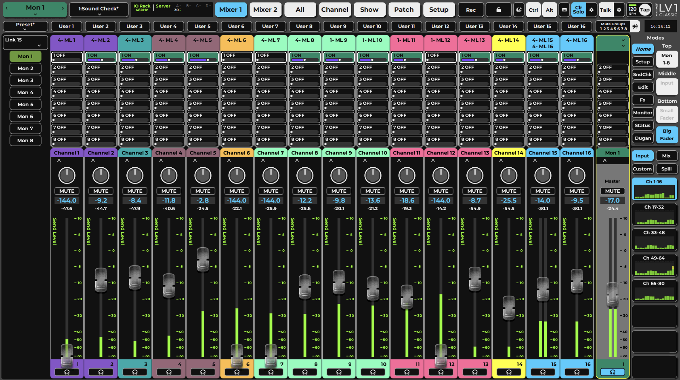
Sub Views aux listIn the Sub Views section on the left, click the name of the aux channel you will be sending to.
-
Send Level fadersWhen the console is flipped, “Send Level” appears next to each large fader; the large faders now control the send level from the selected channel to the selected aux.
-
Aux MasterThe selected Aux flip's master is mapped to the mixer master fader. Cue will be automatically set for the Aux master for quick audition.
The interface changes color to indicate that the channel faders have flipped function. To remind you of the mode, “Send Level” appears next to each large fader. Large faders now control the send level from the selected channel to the selected aux.
To return to normal faders, click on the aux send name, either on the left side of the panel or above the Master fader. You can select another AUX channel while the faders are flipped. This will remap the faders to the new aux sends
Flip From the Fader Bank
- Press Flip on the right side of the fader bank. The top row of buttons (Select/User) turns green and starts blinking, as does the Flip button.
- Use the Layer buttons on the right side of the fader bank to choose an aux layer (e. g., FX 1–8, MON 1–16).
- Use the Channel Select buttons to select an aux to send to.
- Once an Aux channel has been selected, its button turns white.
- Use the Channel Select buttons to choose another aux channel.
When in Sends Flip the channel faders controls the Send level and the channel encoder knobs default to Pan control, which serves as the send pan.
While the mixer is in sends-on-fader mode, the master fader controls the output of the Aux channel. The name of the selected aux channel will appear above the master fader, and cue will be selected for that aux buss.
Once you have finished adjusting sends, click the Flip button to return to the normal channel faders.
Legacy Pan Note: If you send a mono input channel to a stereo AUX Channel (or IEM), post pan (PSP) the send panner is redundant and so will not be displayed. If, however, you created a session with an older LV1 version using that panner, the session will open in Legacy Send Pan mode ON. When Legacy Send Pan is disabled, all the values of mono PSP panners in a pre-v16 session will be reset, and the redundant panner control will be removed from the interface. This action cannot be undone.
Small Fader Mode

Small Fader mode provides a Fader and a Meter (-144 to +10 dB) , Mute and Pan controls in a compact layout that fits a single row, allowing for more modes to be accessible while retaining monitor and control over the channels. Aux Sends on Faders Flip also affects these faders and changes them into send level faders.
Big Fader Mode
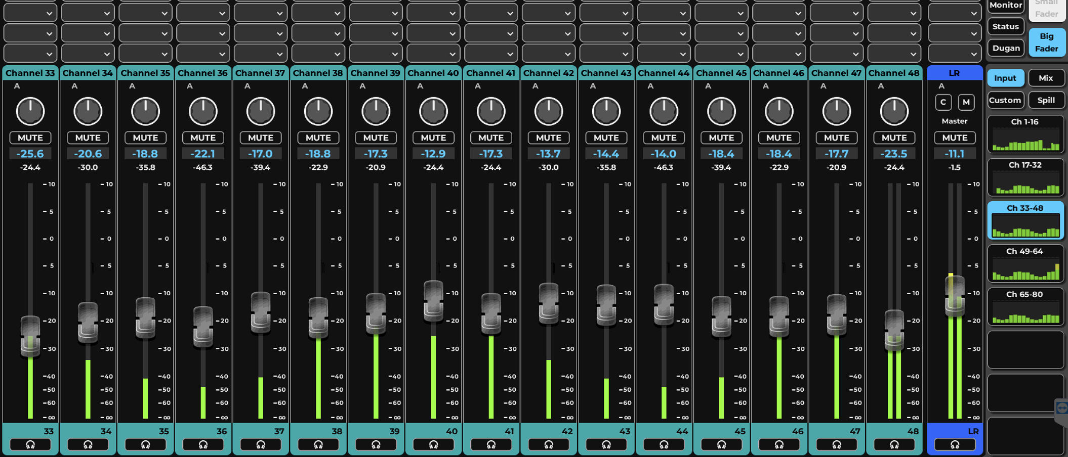
Big Faders Mode brings the large fader and meter to focus and overrides the Middle and Bottom rows, providing a touchscreen workflow fader interface similar to the original LV1 layout. When Big Fader Mode is turned Off, the Middle and Bottom Mode rows become active again.
The Big Fader. mode is the one to use with remote tablet contorol and when critical meter monitoring is required.
The Big Fader Mode provides Pan and Mute control. Fader and Meter range -144 to +10 dB, and have dedicated value box that display the current state.
Big Fader is also used for Aux Sends-on-Faders Flip mode and work as send level controls.
Channel Focus Mode
The Channel Focus mode provides comprehensive feedback and control over routing and processing for a selected channel or buss on the current layer. The Channel Focus is a subset mini-display of the Channel Window and provide quick access to the most used parameters This mode is particularly well suited for single-display mixer setups.

-
Input sectionAll Input controls are addressed here with the same options as avaiable in the Input Mode.
-
Plugin RackAdd, remove and modify the processing plugins in the channel strip process chain. Click on a plugin name to open it for edit in the Chanel window or select from the menu to float it on an independent window.
-
Filter and DynamicsControl the Filter and Dynamics most used parameters.
-
EQControl the EQ most used parameters.
-
Output DisplaySelect the Output Display between Sends and Routes for the channel in focus.
-
Route / SendsRoutes and Sends can be controlled and set in this section.
-
OutputA small Fader, Pan and Mute control for teh Channel in focus.
eMo Immersive In-Ear Monitoring

eMo IEM enables immersive 360-degree panning for in-ear monitors. This delivers a monitoring experience that is, for most musicians, more comfortable, especially during prolonged use. It is intended for MON aux mixes, but it can be used on any Aux channel (FX and Monitor).
eMo IEM requires a separate license. The software License must be installed and activated to be available to LV1 and Mobile apps. Use Waves Central to purchase and manage all Waves software products.
To select eMo IEM monitoring from Mixer window, follow the steps outlined below.
Method one
- Select an Aux Channel (FX or Mon).
- Open the Input drop-down menu at the top of the aux mix and select Channel Config > IEM.
- All source channels in this aux mix will switch to IEM mix mode, Pan knobs will be replaced with 360 'over head' imagers.

Method Two
- While in GROUP/FX or a MONITOR layer, select eMo IEM mode.
- Click ON to enable eMo IEM on the desired mix.
- All aux channels in this aux mix will switch to the IEM immersive mode.
Immersive monitoring requires a stereo AUX channel. If you activate IEM on a mono AUX, the Channel will flip to stereo binaural mix mode automatically. eMo IEM can also be initiated from the Channel window.
You can use Waves on-stage monitoring tools for mobile devices, like MyMon and MyFoh to control the immersive mix directly. Visit Waves.com to learn how use your device with LV1.
Dugan Speech Channel Strip Mode

The Dugan Speech Automixer controls a group of live microphones in multi-speaker environments. It turns up mics where someone is talking and turns them down where people are quiet. It’s commonly used in roundtable discussions, talk shows, debates (and similar setups) and is based on the hardware Dugan Automatic Microphone Mixer.
A Dugan Speech license is required to use this feature, use Waves Central to install the license.
To access the Dugan Layer, click the Dugan Mode Preset, or choose Dugan on any of the mode menus.
- Click the main On button at the left side of the Dugan Mode row under the Dugan logo, to activate the Dugan Speech automixer.
- Click the On button at the top of the Dugan channel strip control to activate Dugan Speech.
- The automixer’s position in the signal flow of a channel is after processing, after fader. Effective automixing depends on correct input gains for each channel. Adjust each channel’s preamp or input gain so that the level display is green. If needed, lower the master fader to compensate for the sum level of several channels.
- Click the Auto button to turn on the automixer for that channel.
- Set the weight controls to balance the channel auto mix gain and establish the priority of one speaker over others. Weight levels can be changed by dragging the faders up or down, or by entering dB values in the value boxes below the faders.
Assign channels to Dugan groups. A group functions as a separate and independent automatic mixer. Each channel can be assigned to one of three groups: a, b, or c. Dugan groups control mutes in the same manner as LV1 mute groups.
Mixer Layers
A mixer layer is a collection of channels that share a common function. Layers differ from modes. A layer determines which channels you want to address, while modes determine what you want to do with the channels in the layer. There are layers that contain fixed channels, and custom layers that you can populate with any combination of channels. Select between layers with the selection buttons.
The eMotion LV1 Classic 80-channel configuration provides 40 channels of groups and auxes. Depending on the needs of your show, you can allot 16 groups and 24 auxes or 8 groups and 32 auxes. The 64-channel configuration provides 8 groups and 24 auxes. You can change the configuration at any time. Mixer configuration is set in the Mixer Settings page. The 80-channel expansion requires a separate license.
Layer Banks
Each Layer Bank holds 8 layers of 16 channels each. Up to the 64 channel configuration, the Factory layer layout fits in one bank, while higher channel count configuartions split the Factory layout to Input Layers Bank and Mix Layers Bank.
Custom Layers Bank can be slected for
fully customized layout of all avaiable channels.
Spill Layers mode can be activated here.
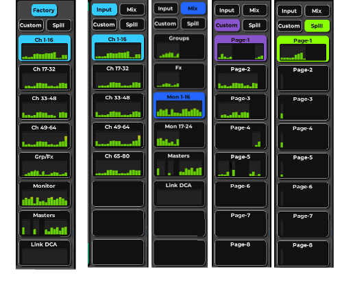
Factory Input Channel Layers
The factory mixer layers are accessed from the Input button on the right panel. These are the input channels that feed the mixer. An input channel can be mono or stereo, and this does not affect the total number of channels available. Input channels can control I/O preamps (depending on input device), and each input channel can have up to eight plugins. They can be routed to groups, matrix, main, and direct outs, and sent to Aux FX and Aux Monitor channels.
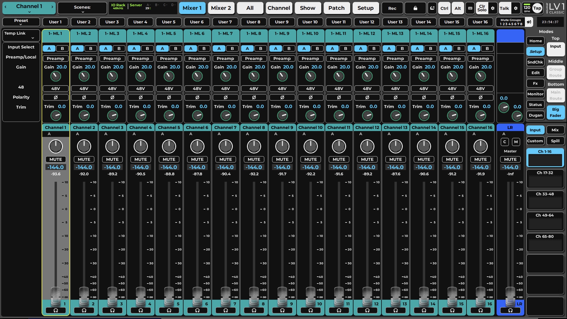
These Five layers share the same view and functionality. Only the channels change.
Group Layer
Click the MIX button above the Layers to access the GRP FX, MONs, Masters, and Link/DCA layers.
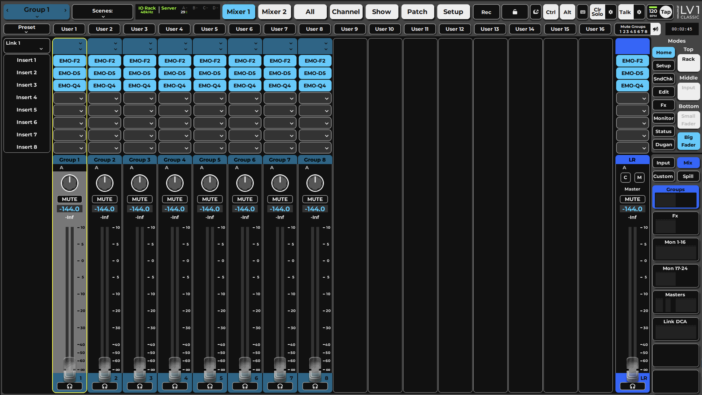
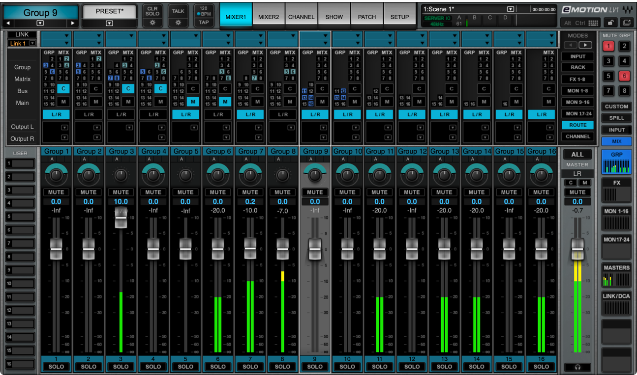
A group can be routed to another group for additional processing. A low-numbered group can route to a group that is later in the signal flow, but not earlier. For example, Group 4 can be routed to Groups 5–8, but not to 1, 2, or 3. Groups can be set to process pre-FX or post-FX to create and process mix groups that include dry inputs with effects.
Group busses are mono or stereo. The default mode is stereo. There are two ways to set the group buss to mono or stereo:
- Use the MIX MODE: MONO / STEREO button in a group’s input panel on the Channel window.
- Use the input device menu in the GRP/FX layer of the Mixer window.
Each Group buss can accommodate up to eight plugins.
FX Layer
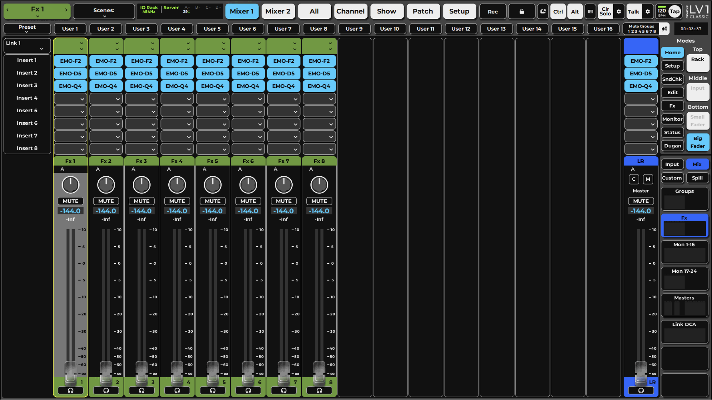
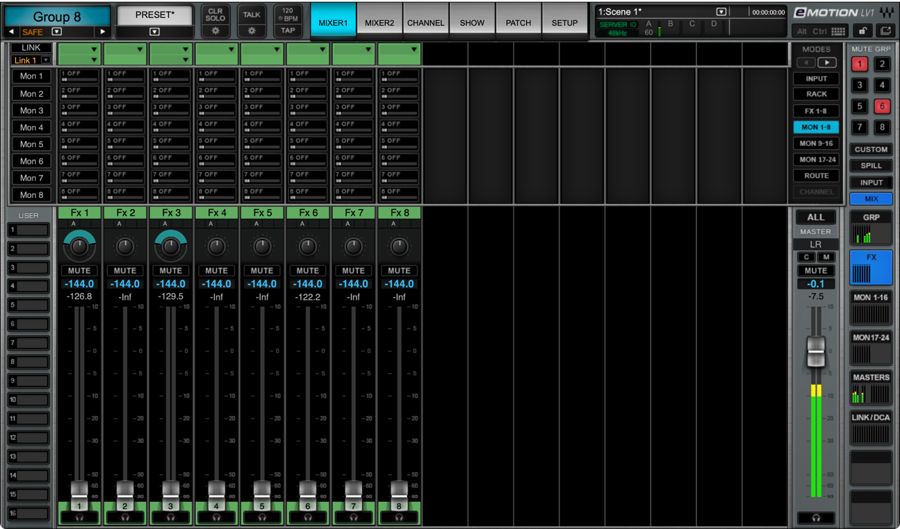
The eight FX busses are used to process signals that will be sent to monitor outs or other paths. You may choose to process an FX aux buss and then send it to one or more MON busses. This way you can efficiently perform effects processing that can be used over several monitor outs.
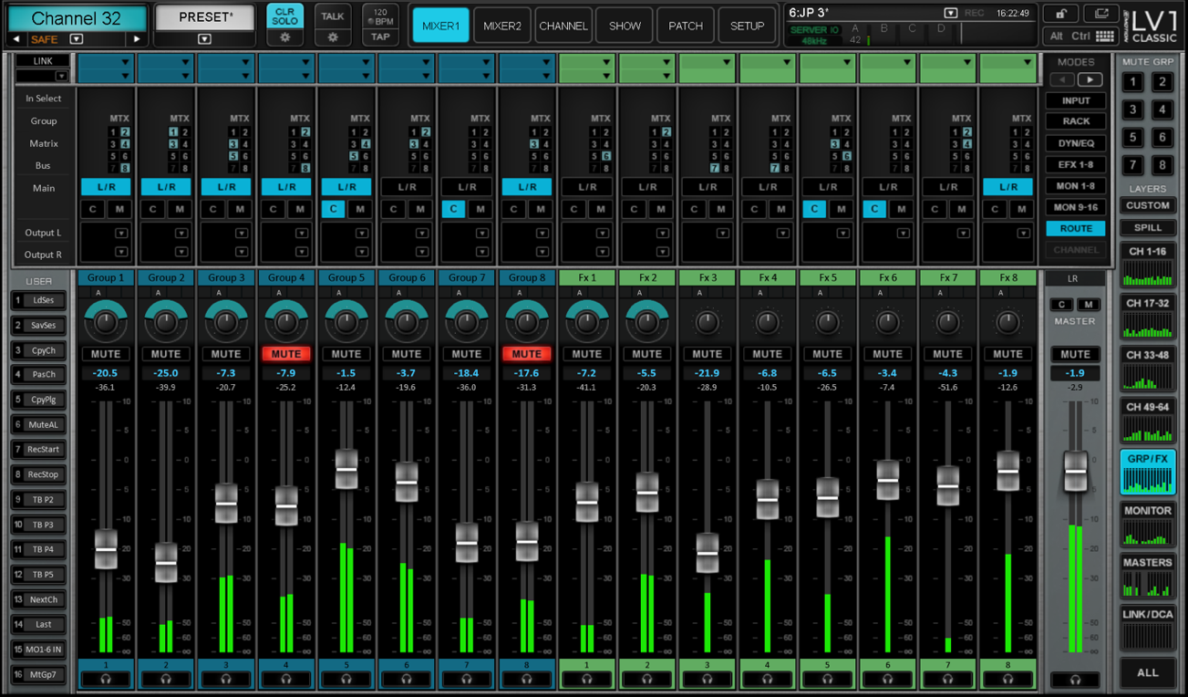
If needed, some FX busses can be used as monitor outputs (within limitations of available sources). In addition, monitor busses can be used for more effects processing and routed to the main mix rather than a monitor (IO device).
All AUX/MON and AUX/FX busses can be stereo or mono. This is determined by the format of the buss you are sending to, not the one you are sending from.
Monitor Layer
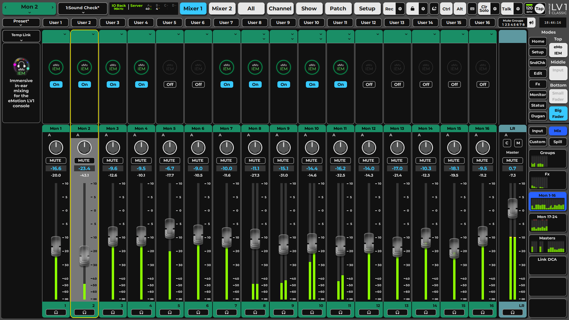
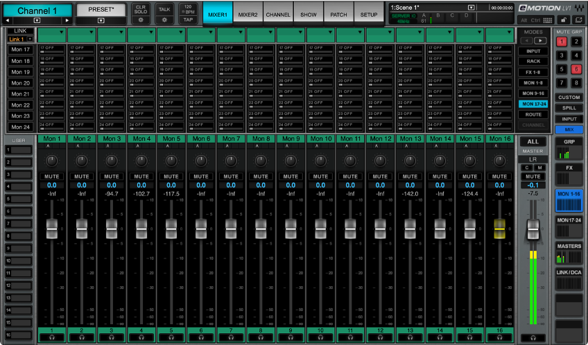
MON busses are typically used for monitor feeds. Signals are sent to the MON busses auxes from groups and FX. Each monitor aux can include up to eight plugins, so processing can be added to an aux buss before it is routed to an I/O. Monitor busses can be mono, stereo, or immersive.
If needed, some FX busses can be used as monitor outputs. In addition, monitor busses can be used for more effects processing and routed to the main mix rather than a monitor (directly to an I/O device).
Assigning aux sends is discussed later in this chapter.
Masters Layer
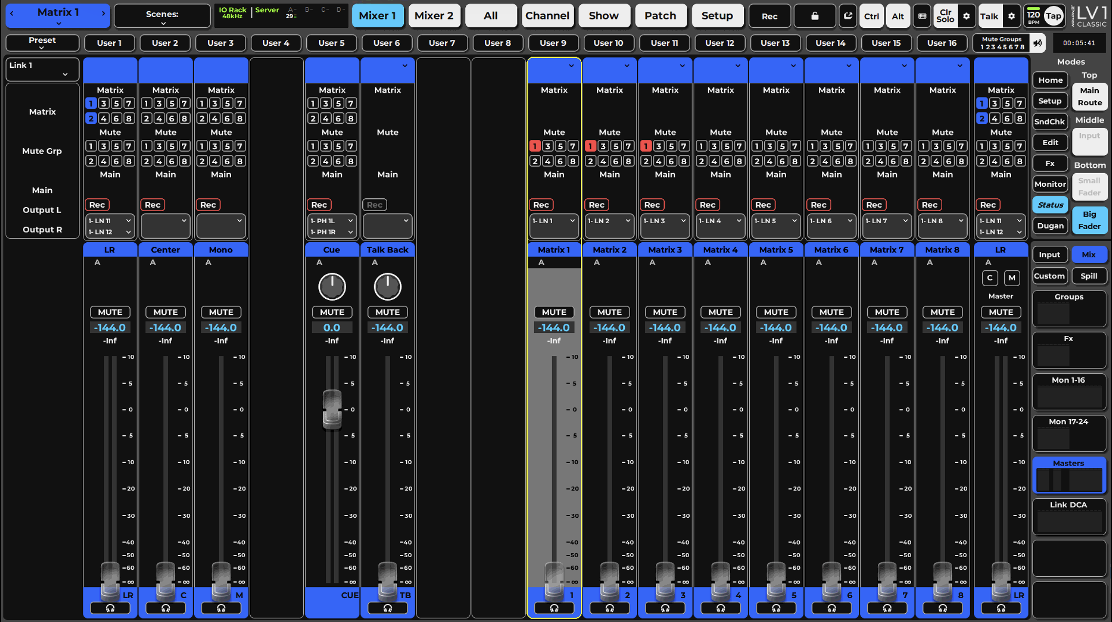
The Masters layer provides control over the Main mix and its distribution, as well as Matrix, Talkback, and Cue. The Main and Matrix busses each use up to 8 plugins to adjust the distribution properties of each mix output, such as the PA system, peripheral zones, or guest sends. The Layer is divided into two sections: Mix buss outs (Main outs, Cue, and Talkback), and a Matrix (12 stereo inputs per channel, with eight stereo outputs).
Main Mix
Main mix outs can be assigned from any mixer channel or buss, except Cue, Matrix, or Talkback. To quickly learn which busses are assigned to the Main out busses, check the Internal Patch page or open the Input list in the Channel window of a Main out.
- The Master fader on the right duplicates L/R fader position.
- In the Input mode, Center and Mono channels have input-independent trims.
- Hosts up to eight plugins.
- All Main mix busses can be assigned to the matrix.
Cue
When a channel’s Cue button is engaged, assigned busses are sent to the cue buss. This section controls level, panning, and processing of the cue buss.
- Cue/solo mode can be activated from any channel (except Cue).
- Cue operating mode and sources are controlled in the Channel window. Click the Gear icon beneath the Clear Solo button in the Top Bar to access the Cue control panel. Buss and I/O assignments are also made from the Channel window.
- The Cue channel can host up to eight plugins.
- Refer to the Channel chapter for details about the Cue buss settings (Channel > Cue Section).
Talkback
The Talkback section controls the level, panning, and processing for mixer talkback. It provides for input from an I/O and a preamp. It can accept up to eight plugins. Talkback routing and presets are controlled from a control panel in the Channel window. To access this window, select the Talkback channel and click on the Gear icon beneath the Talk button.
Matrix
The Matrix controls the input mix and output levels of the 12-input x 8-output matrix busses. It is typically used to send audio to PA systems, distribution, guests, and monitoring systems. Matrix channels can receive input from any channel or buss in the mixer and can output to any I/O device on the network. Each Matrix channel has an eight-plugin rack for dedicated processing.
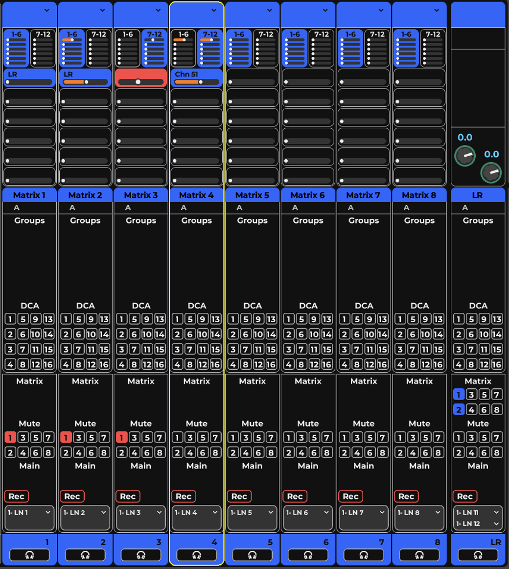
Each Matrix channel accepts up to 12 assignments. Assignment levels can be controlled using the small faders on each Matrix channel (Input mode), or, more conveniently, in the Matrix channel page. To access this panel, select any Matrix channel and navigate to the Channel view.
Link/DCA Layer
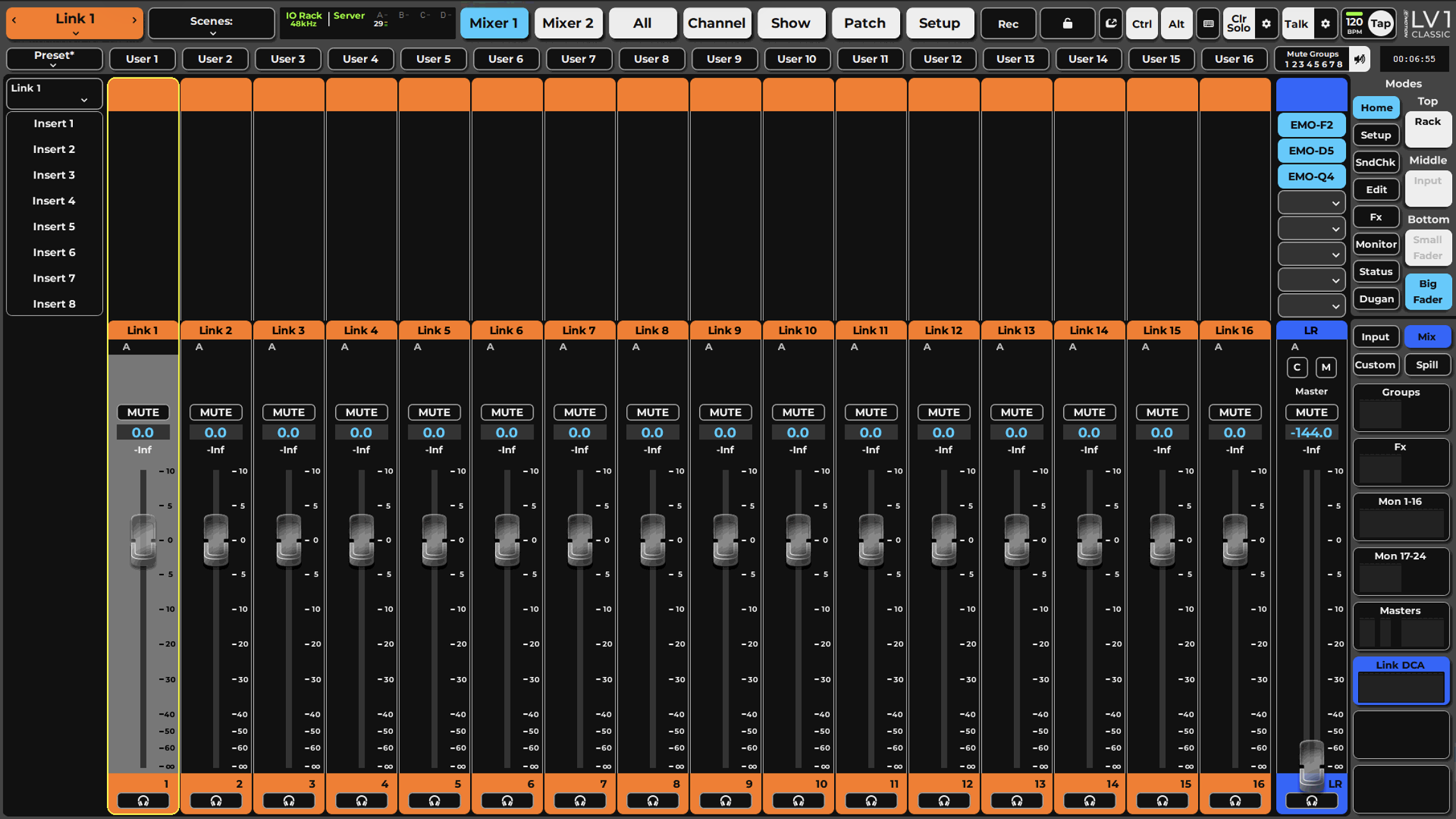
The Link/DCA layer does not pass audio. Instead, it’s a controller that’s used to manage groups of channels.
While both Links and DCAs allow you to control a group of faders and adjust their gain together, they work in very different ways.
Channels are assigned to Links and DCAs in the Output section of the Channel window.
Link Group Controls
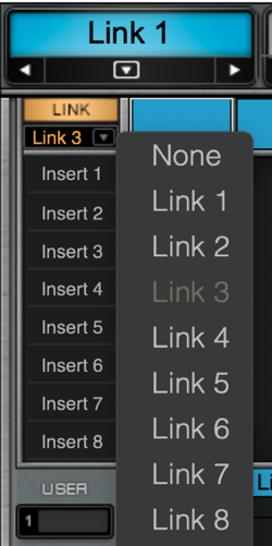
Links provide a way to globally control values across multiple channels. When channels are assigned to a Link, most of their controls move together. Adjusting one fader causes the other faders in the group move correspondingly. The Link button and menu are used to activate and deactivate linking and determine which Link group is currently active.
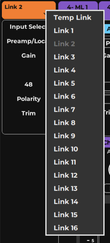
- Any mixer channel can be assigned to a Link group.
- There is no limit to the number of channels that can be assigned to a Link group.
- All mixer controls present in the Channel mode can be linked. Compressor sidechains, for example, are not linked.
Relative offsets between controls are maintained when any group member moves.
Channels in the active Link group are identified by small numbers beneath the channel name. A Link group is active only when its group is displayed, so only one Link group can be active at a time.
A channel can be assigned to up to 16 Links. Channels in the active Link group are identified with small numbers near their panners. A Link group is active only when the Link button is On and its group is displayed, so only one Link group can be active at a time.
To change the value of a control with respect to other members of the Link group, turn off the Link button, make the adjustment, and then reactivate the Link group. Faders that are members of a Link group behave as do any other linked controls—move any fader in the Link group and the other faders follow.
Link Follow Channel Select Selects link behavior when switching between link groups. (Links apply to faders, pans, and mutes).
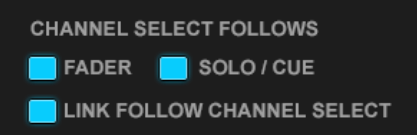
On: When you have more than one link group, changing the channel select activates the new link. This is akin to selecting a new link in the Link drop-down menu. Only channels in the newly selected link are activated.
Off: When you select a channel in another link, the link selection will remain tied to the original channels, but the new and old channels can each be adjusted.
Temporary Link Group
A Temporary Link lets you simultaneously adjust parameters on selected channels without setting up a formal Link group. You can gang together any controls that can be adjusted in the Channel Mode. Temporary Links are not stored in the session; they are active only until you stop the link. To create a temporary Link, follow these steps:
- Click the Link button to activate Link. The button will flash, and Temp will light up. Temp assignment is now active.
- Select the channels you want to group together. Channels in the Link group will display a “T.”
- Once this temporary group is defined you can adjust any control that is displayed in the channel mode).
- While in this mode, you can remove or add channels from the Link group.
- To stop temporary linking, click the Link button again.
To quickly link numerous channels across many layers, use the All Mixer view for ad hoc group assignments.
DCAs
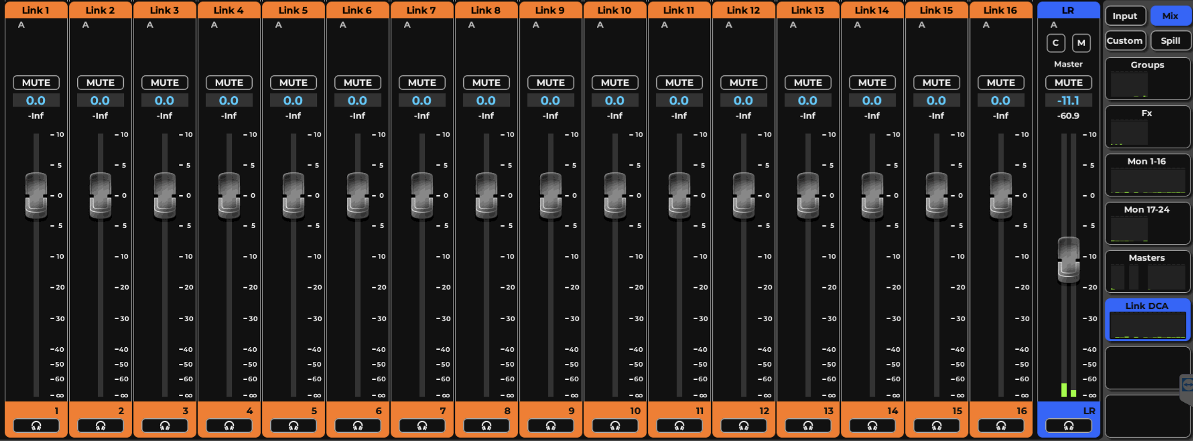
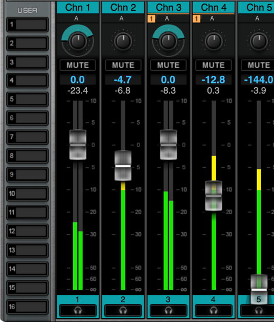
A digitally controlled amplifier (DCA) controls the volume levels of the channels assigned to it (the Link groups) without changing the fader positions. This allows you, for example, to remotely control channels as a group without affecting their individual processing.
The DCA group control is from the Links/DCA layer faders rather than from individual faders on the mixer layer.
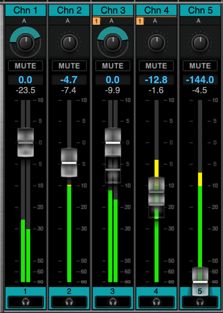
A DCA fader applies an even-gain offset to all the faders assigned to it. When the DCA fader is set to zero, the channel faders under its control are unchanged.
Its advised to check the Link button state when using DCAs, as the Link may cause paramter chanegs on memeber channels, while DCA only creates an offset.
When a DCA fader moves, the linked faders do not physically move. Instead, a “ghost” fader indicates the combined gain achieved by a channel’s faders and the DCA offset. This is similar to the behavior of analog VCA faders.
The DCA faders also provide a Mute function that behaves like a Mute group.
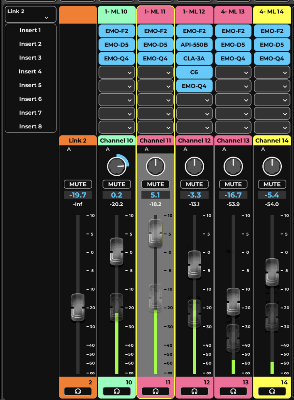
When DCA is moved on the Link/DCA Layer, the faders for Linkd channels do not move, but “ghost” faders indicate the offset created by the DCA gain.
DCA faders range -144 to +10 dB offset on the Faders assigned.
Spill Layers
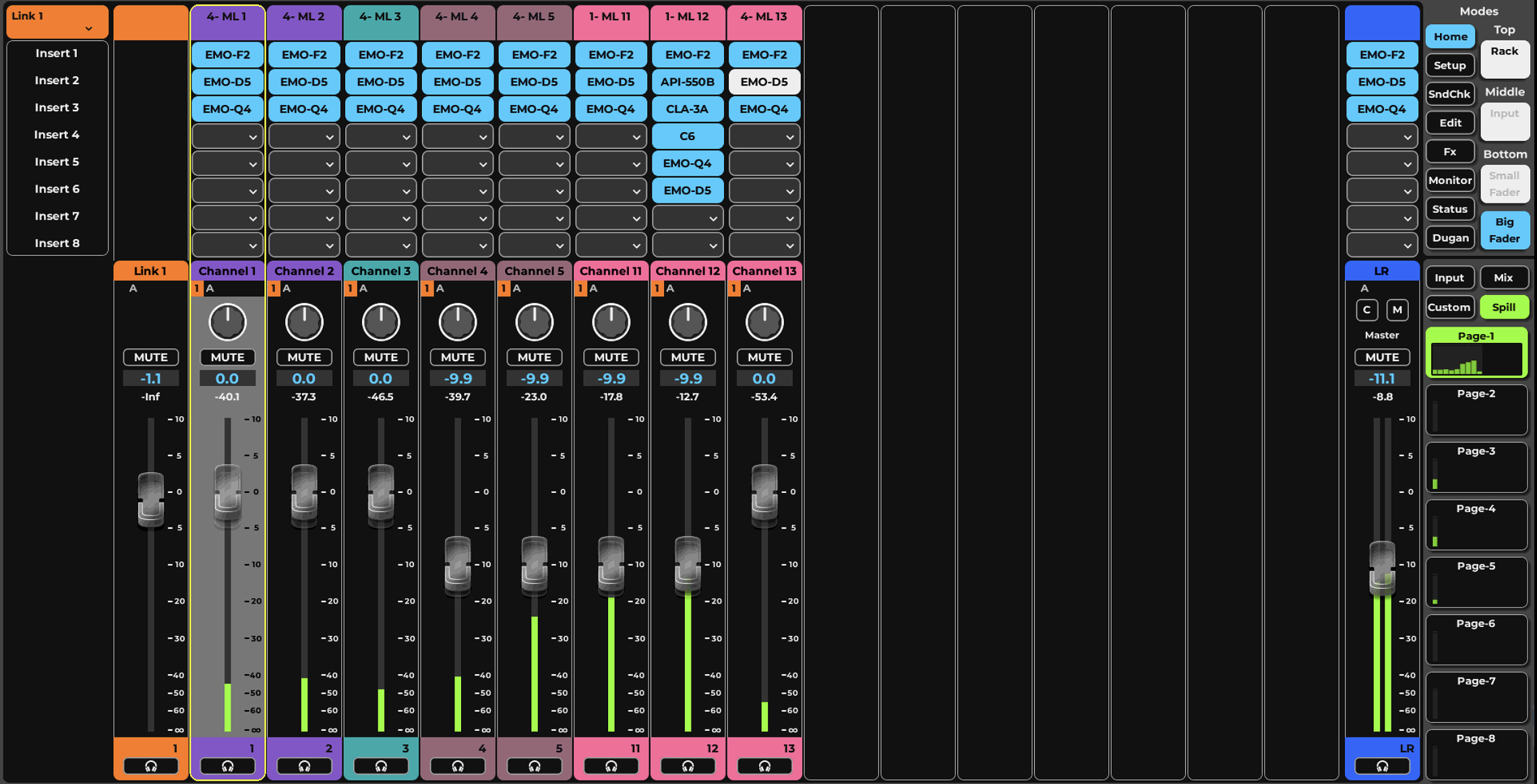
The Spill layer displays all the channels in the selected Link Group, regardless of the channel types. Linked controls can be adjusted and a DCA can be used to trim all faders in the group.
The Spill button is located on the Layers panel. Click the Spill button to access the view. Select a Link/DCA channel on the left side of the mixer to view its associated Spill pages.
Navigate between Spill pages with the Custom layer buttons on the right. Double-click on a button to rename it.
Each Spill page (shown below) has 16 channels: the DCA fader is on the left, and 15 linked channels are to its right. If a Link group has more than 15 channels, then multiple pages will be displayed.
The Link On/Off button does not affect the Spill function. It only reflects the status of the Link group.
Custom Layers
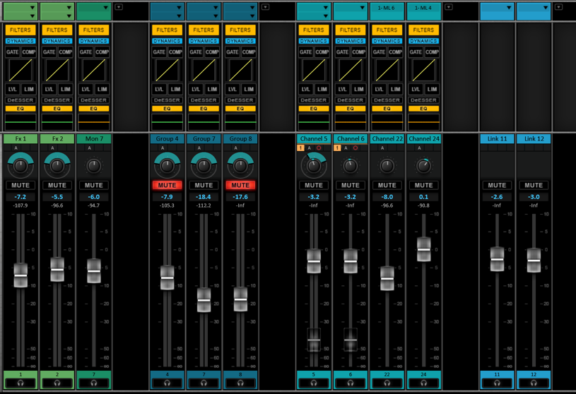
Channels of any layer type can be combined in user-created Custom layers. This enables control of a specified assortment of channels in one view, without changing mixer layers. Channels can be organized in any order within a Custom layer. Each of the eight Custom layers can contain up to 16 channels.
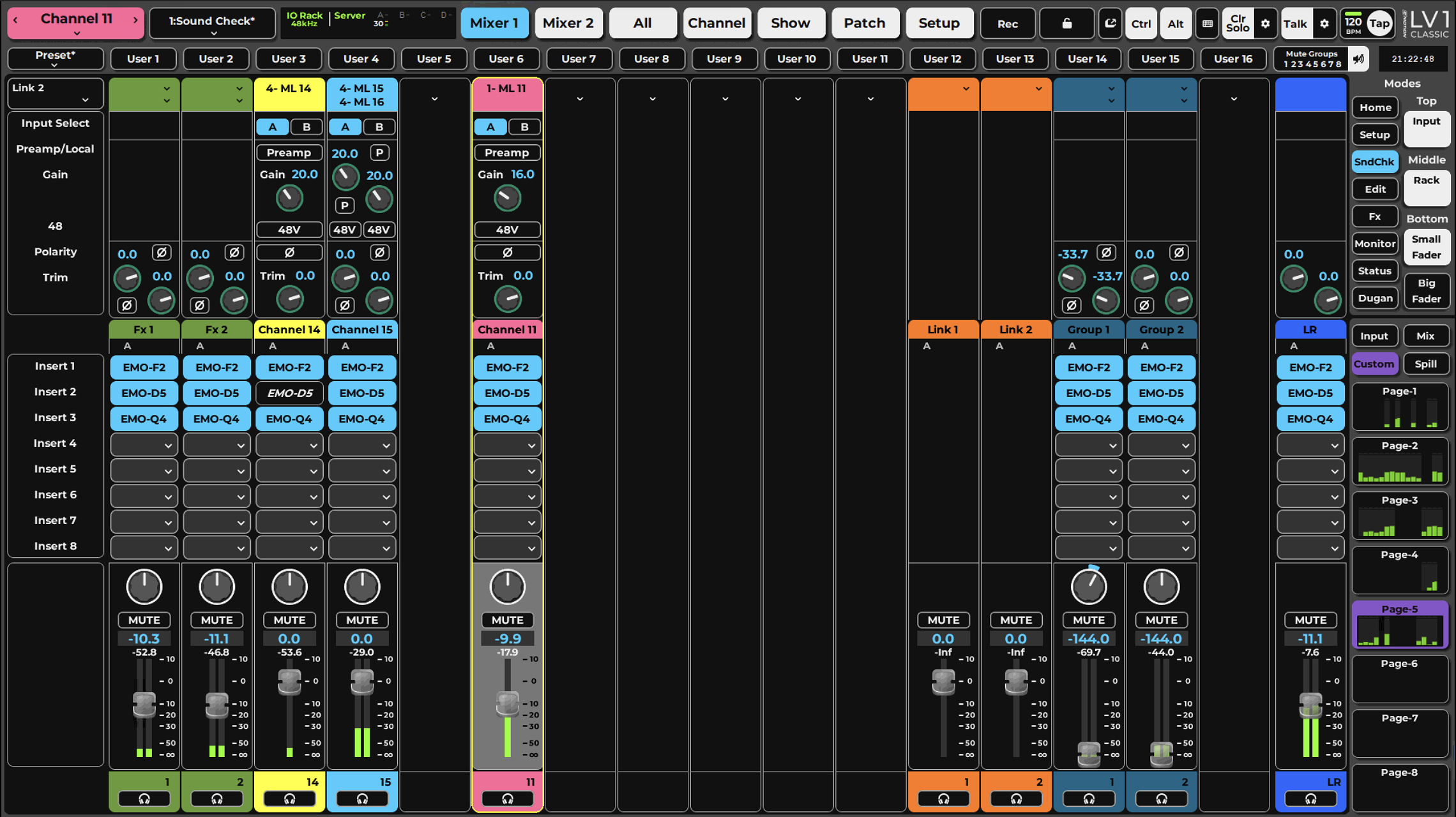
To populate a Custom layer, click “Custom” and choose one of the eight Custom layer buttons. The layer will initially be blank.
- Use the drop-down menu at the top of a channel strip to open the Custom assignment menu. Select the assignment.
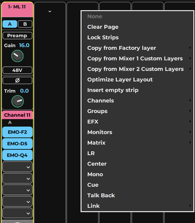
- Click and drag on the channel to rearrange the channel strips.
- If a channel strip is already populated, Ctrl+click on the channel name (or use the arrow on the top-right corner of the strip) to access the Custom layer menu.
- To rename a Custom layer, Double-click on a Custom layer page button.
- Repeat the assignment process for up to eight Custom layers.
Use the menu items at the top of the assignment menu to populate and manage each Custom channel.
- None: Removes the selected channel page from the custom layer.
- Clear Page: Removes all channels from the custom layer.
- Lock Strips: Prevents channel strips from being repositioned.
- Copy from Factory Layer: Copies all channels of a mixer layer and pastes them to the custom layer.
- Copy from Mixer 1 (or 2) Custom Layer: Copies any page from a custom layer in either mixer and pastes it to the custom layer.
- Optimize Layer Layout: Removes blank channels and moves all populated channels to the left.
- Insert Empty Strip: Inserts a blank strip to the left of the selected populated strip.
- List of channels to populate the page
Chapter 3: ALL MIXER OVERVIEW
The Mixer Overview page provides basic control of all channels, busses, and links in a session. Each channel and buss has its own small channel strip that includes Cue, Fader, Meter, and Mute, as well as Link and Record indicators. so it’s useful for confirming audio presence and level and making basic adjustments. Aux modes can be selected, and you can enter the sends-on-faders mode from the menu.
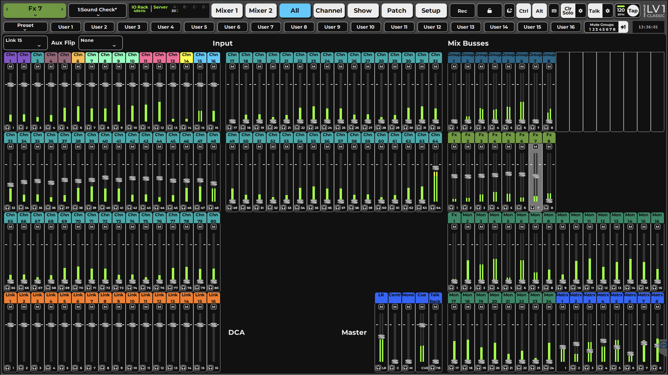
Click the ALL window tab button to toggle the All Overview on or off. The ALL view is useful for single-display configurations, since you can easily go from an overview of all channels to a Channel or Mixer view, and back. Undocking the All window to an external screen enables you to work with two or more displays and see an overview of all channels on one display, while working on single-channel or mixer views on the others.
The layer types are labeld, while each channel displays its selected color.
Aux Sends-On-Fader Flip
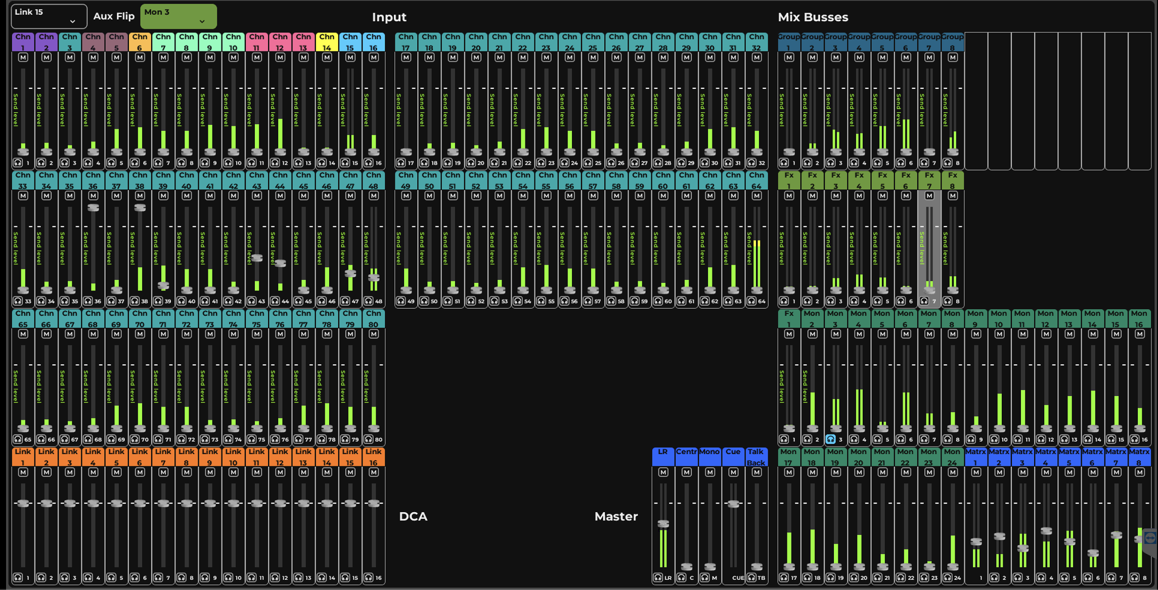
When selecting an Aux Sends Flip from the menu, the relevant source faders will get the Aux Sends label and will set the send levels. The Flip mode can be turned off by clicking on the label.
Link Control
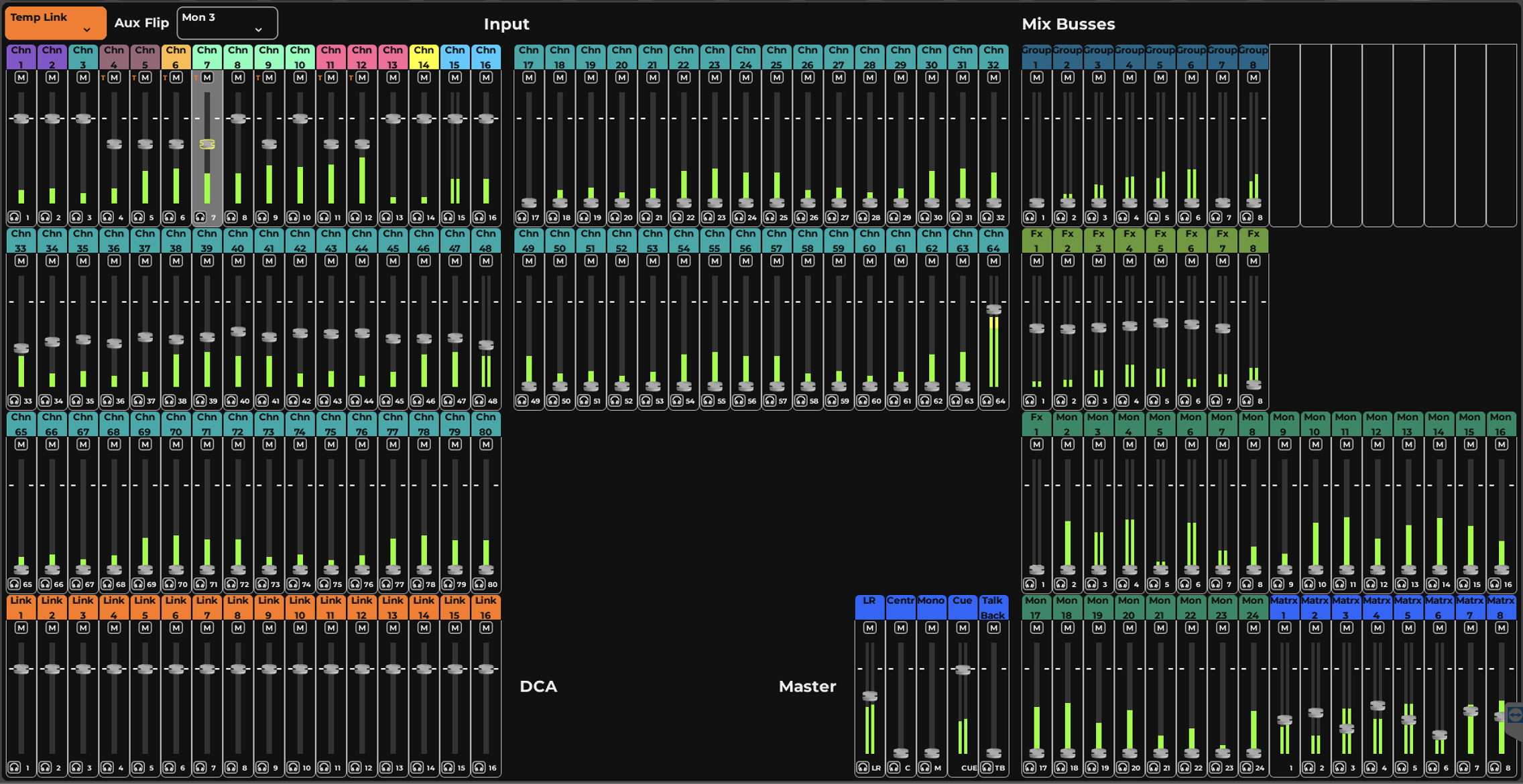
When Link is turned on for a pre set Link group or for Temp Link, the group memebers will be indicated by small orange charachter next to the channel name, moving the fader for one member will relativly move the entire group.
Fader / Meter Settings
The All window can be set to provide full fader control as well as mute and cue, alternatly it can be set to display meters only with no gain indication (Mute and Cue will still be indicated), and an interm mode where fader position is visible but cannot be modified from this window. These options are avaiable in Mixer Settings page in the Setup window.
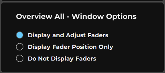
Chapter 4: CHANNEL WINDOW
The Channel window provides a comprehensive view of a selected mixer channel and control over each channel parameter.
Channel Window Sections
The entire chain of the selected channel—input and preamp control, plugin processing, aux sends, routing, and outputs—is addressed in this window.
The Channel window is divided into sections that represent the signal flow through a selected mixer channel. Workflow from section to section generally progresses from left to right.
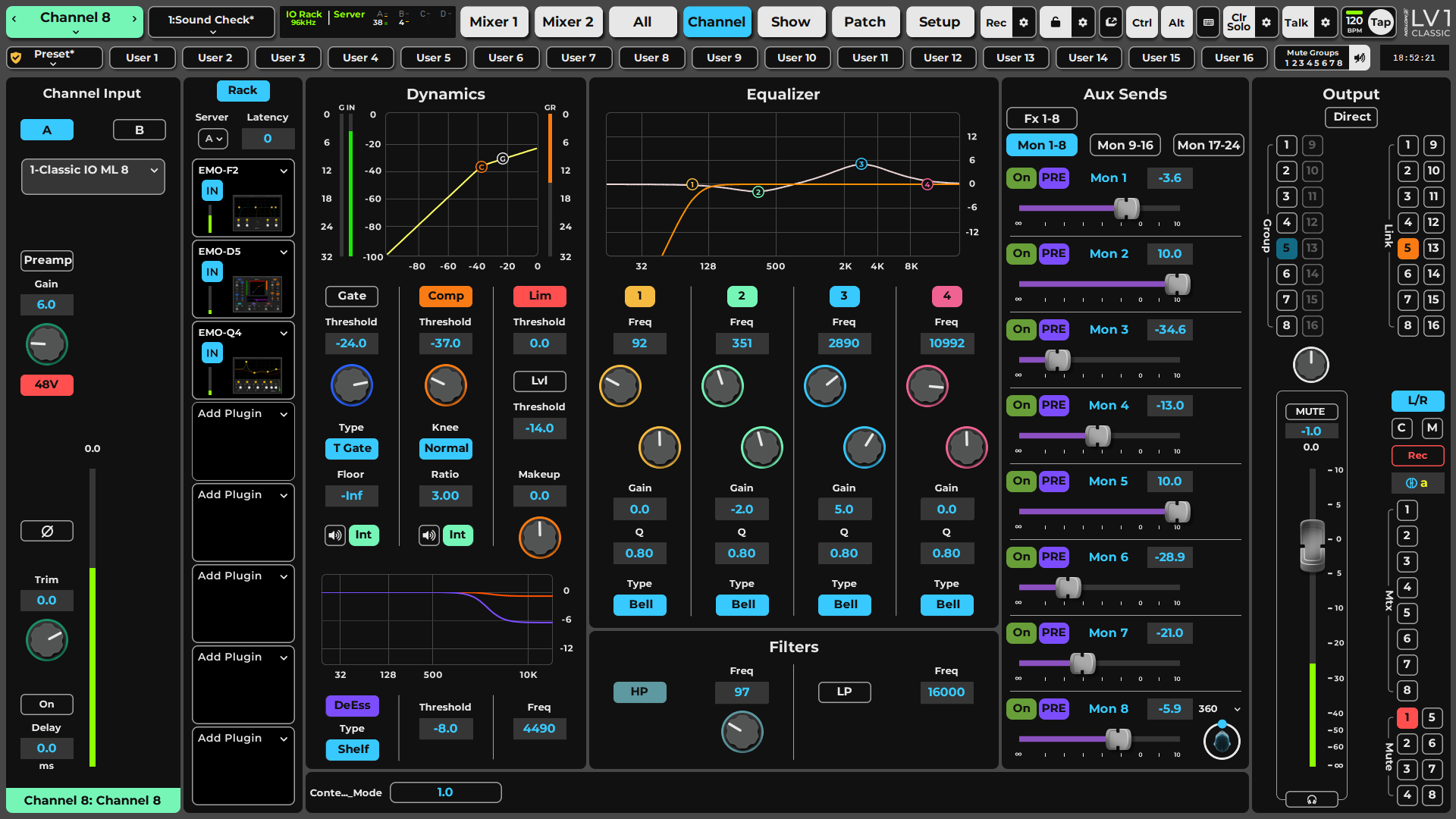
-
InputManages channel input, including source, preamp control, digital input gain, high pass and low pass filters, and input delay.
-
Plugin RackAssigns, removes, and controls up to eight plugins per rack. Clicking on a plugin icon will open the plugin for edit in the Channel window. Plugin menu provides control and information about the plugin state in the session.
-
Main Control Section - DynamicsThe Main Dynamic Control section maps to the channel assigned dynamic processor, by deafult eMo D5, providing the channel dynamic facility for Gate, Compressor, Limiter, DeEsser and Leveler. The controls in this section are reflected in the Mixer modes and can be controled from the correlating fader bank encoder section, when set to Edit.
-
Main Control Section - EQ and FiltersThe Main EQ and Filters Control section maps to the channel assigned EQ and Filters processors, by deafult eMo Q4 and eMo F2, providing the channel HiPass and LoPass facility for filtering and 4 band Parametric EQ. The controls in this section are reflected in the Mixer modes and can be controled from the correlating fader bank encoder section, when set to Edit.
-
Main Control Section - Aux SendsAux Sends to FX and Monitors are setn this section, in banks of 8 sends, each can set the source pick off point, send level and panningwhen applicable.
-
OutputManages all internal buss assignments, Mute groups, DCA Link groups.This section includes the channel main output Fader, Mute,Solo/Cue and Pan. By clicking the List button, the section will display the list of extrenal outputs providing control for source, trim and delay for each.
-
Channel Name and Preset MenuChannel name and preset menu are part of the Top-Bar, but affect the Channel settings. This is where you select the channel. Its name is displayed in the box and can be viewed form any menu. To select a channel on the fader bank, choose “Ch Select” above the master fader and select a channel. From the touchscreen, click the left/right arrows to navigate to adjacent channels. Use the drop-down menu
Channels and Presets
Selecting a Channel
The selected channel is focused across LV1 Mixers and Channel windows. The selected channel name is always shown in the Name box on the left side of the Top Bar. To name a channel, double-click on the box. The channel name can also be changed in the Mixer and Patch windows.
A channel can be selected in several locations:
- Mixer Window: Touch a channel strip on the screen. The channel strip becomes highlighted, indicating that the channel is selected.
- Fader Bank: Use the Channel Select button at the top of a channel strip.
- Fader Bank or Screen: Touch a fader (Channel Select Follow Faders must be On in the U/I Settings page).
- Fader Bank or Screen: Touch a Solo button (Channel Select Follow Solo/Cue must be On in the U/I Settings page).
- Top Bar: Use the Channel Navigation menu in the Top Bar to directly access a channel. You can also use the right/left arrows to move the selection up or down one channel at a time. This menu is always visible.
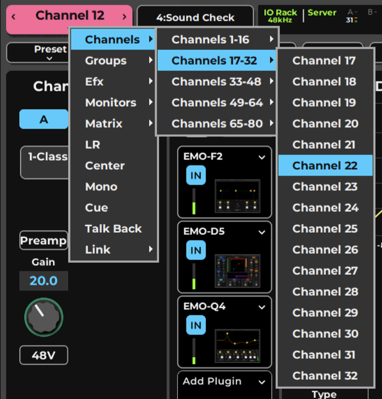
Channel Presets
Channel presets are managed in the Preset menu in the Top Bar. These presets allow you to immediately load all of a channel’s settings (i.e., audio routing, assignments, plugins and their parameters, aux sends, and control groups) and then adjust its parameters. You can save these settings as a new preset.
Complete sessions can be created from channel presets, or you can copy/paste channels to use as starting points for other channels. You can copy all or part of a channel’s parameters from one channel to another.
Preset Menu Items
Factory Presets (load) | A library of presets supplied by Waves. A factory preset cannot be modified. Instead, open it and save it as a user preset. |
User Presets (load) | A list of user-defined channel presets saved within the current session or imported from another. These presets load all channel parameters. To delete a user preset, hold Ctrl/Alt before opening the Preset menu—preset names will be preceded by a “Delete” option. Select the preset to delete it permanently. This action cannot be undone. |
Import from File | Opens a navigation window to locate presets files that have been saved. Imported presets are added to the User Preset menu. |
Paste | Pastes a copied channel preset to another channel. The Copy command copies all channel information, and Paste allows you to choose what channel information is replaced in the target track. |
Save | Saves the current channel condition to the loaded channel preset, overwriting it. |
Save to User Presets | Creates a new user preset. These are saved as part of the current session. Consider this a Save As function. |
Rename Preset | Changes the name of the current channel preset. |
Save to File | Creates a file that is saved at a user-defined location (file extension: .xps) and can be imported to any session. Unlike user presets, these are not embedded in the session. |
Copy | Copies the current channel condition. A copied channel preset can be pasted to any other channel in the current session. |
Set Channel Color | |
Channel Recall-Safe Off | Temporarily excludes all channel parameters from scene changes, even if they are within the scope of the scene change. |
The remaining Preset menu items relate to sessions and templates. These are discussed in the Top-Bar and Show chapters.
When pasting or importing presets a Preset Scope dialog pops up to set which functions to import from the selected preset.
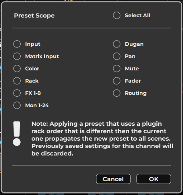
Channel names can be copied within a session. Channel names and colors cannot be imported from another session.
Copying channels between Sessions
To copy channel settings between sessions, use Save to File to create a channel preset file. This file can be saved at any location, including removable media.
Select a target channel and choose Import from File. This replaces all channel parameters. It does not alter the number of input channels.
Copying and pasting channel parameters within a session is very similar to saving and importing files between them. There are, however, important differences:
- When pasting a copied channel to another channel in the session, you can choose which parameters to change.
- Importing a channel presets file replaces all current channel parameters.
The stereo/mono status of a channel is determined by the current state of the target channel, not by the pasted/imported channel parameters.
Set Channel Color
By default, channels are color-coded based on types of channels (e.g., channels, groups, FX, monitors). You can also assign a custom color to any channel.
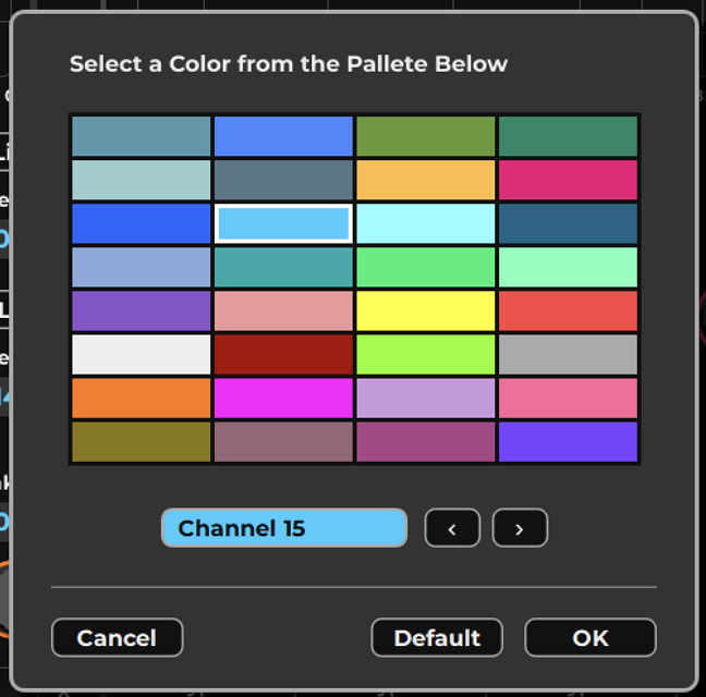
- Select a channel.
- Choose Set Channel Color from the Preset menu to open the Color Picker. The name of the selected channel is shown.
- Select a color. Colors are applied immediately, not upon clicking OK.
- Use the left/right arrows to choose other channels to customize.
- Click OK to exit the window.
Input Section
The Channel Input section is used to patch external sources to Input and internal busses (Group, Aux, Matrix channels). It is also used to link together mixer controls (Link/DCA). Input section function and appearance differ between input, mix, and control channels.
Input Section for Mixer Input Channels
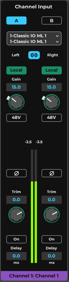
-
Input A/B Select
-
Input Menu and Display
-
Left/Right Link
-
Preamp Analog/Local Gain Toggle
-
Gain Control for Preamp or Local
-
48V Phantom Power
-
Peak Indicator
-
Polarity Reverse
-
Meter
-
Channel Input Trim Controls
-
Input Delay
-
Channel Name and Sequence Number
Device Channels - Select I/Os
The Device Channel selector sets the I/O source for a selected input channel. Choose an I/O source from the drop-down menu. The list is organized by device and then by I/O channel. Unavailable devices and channels are grayed out.
Flip to Mono or Flip to Stereo changes the mode of the channel. When a stereo channel is flipped to mono, the top (left) channel becomes the mono input. When flipping from mono to stereo, only the left channel will be patched. The right channel can then be assigned manually. Stereo input assignment of I/Os is usually in pairs. Ctrl + menu enables independent channel assignment for left or right sides.
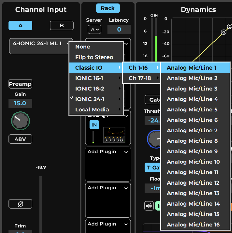
Selected input channel: click to open I/O selection menu I/O devices list I/O channels on the selected device
A/B Input Select
The mixer has two independent sets of inputs: A and B. These inputs can share the same I/O devices and channels or use different ones, as long as all I/O devices are in the system inventory of this eMotion LV1. Define input sets in the Patch page.
Refer to Patch >Patching Mixer Inputs Options: Input A or B
Left/Right Link (stereo channels only)
Links the left and right channels for all Input section controls. Parameter value offsets between left and right are maintained when linked. Default: On
48V Phantom Power
Activates the preamp 48V phantom power. Independent left and right controls. Options: On or Off, default: Off
Preamp Analog Gain Adjust
I/O preamps can be controlled from the Input section. These controls are active only when a preamp is available.
The Preamp section is used to adjust the analog (hardware) gain and the digitally controlled output level of the I/O device’s preamp. There are two modes for controlling preamp gain: Preamp and Local. Select a mode with the button above the preamp control knob.
Preamp mode (left) adjusts the preamp’s analog gain, just like the preamp gain control in the device’s control panel. Preamp analog gain value is displayed above the knob. Characteristics when sharing preamps in Preamp mode:
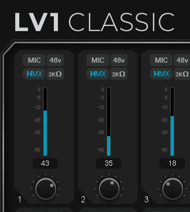
- All users operating in the Preamp mode have direct control over preamp analog gain.
- When preamp gain is adjusted on one system, it will change correspondingly on all systems.
- When a shared preamp is switched from Local mode to Preamp mode, its gain setting will take on the V-Gain level.
Preamp/Local modes
In Local mode, the Gain knob becomes the V-Gain knob (Virtual Gain). V-Gain is a digital gain stage that always delivers the user’s requested input gain, regardless of the preamp’s analog gain setting.
Characteristics when sharing preamps in Local mode:
- Changes to preamp analog gain (Preamp mode) will not affect the channel input gain of any user who is operating in Local mode.
- A channel set to Local mode can adjust its gain without changing the preamp analog gain; Local level is controlled by V-Gain.
- Local users will see a green ring around the V-Gain knob, indicating the difference between the Preamp analog gain and the V-Gain setting.
Preamp state (Preamp or Local) and Gain values are saved with the session and are recalled when the session is loaded. The Gain and V-Gain values can also be stored with scenes. When recalled, the value will be applied to Gain or V-Gain, depending on which mode is active. When moving from Local to Preamp mode, the V-Gain value is sent to the Preamp control, and the preamp takes on the V-Gain value.
I/O Sharing
Multiple eMotion LV1 systems can be connected through an Ethernet switch to create a networked “super system.” Users throughout this super system can assign any available I/O device to their eMotion LV1 system. For details, refer to the Setup window chapter.
Polarity Reverse
Reverses the polarity of a preamp input channel. Independent left and right controls.
Options: On/Off, default: Off
Channel Input Trim Controls
Controls the channel’s pre-processing digital input level. When input does not provide gain control, as in digital input, the Trim is used to adjust gains. Independent left and right controls. Range: -INF to +10 dB, default = 0 dB.
Input Meter Peak Indicator
Displays the meter’s peak level. Red indicates that the user-defined clip threshold is exceeded. Click on the meter or value box to clear. Meter behavior is set at Settings>U/I Settings.
Mono/Stereo Meter
Displays peak input level.
Range: -INF to 0 dBFS
Input Delay
Sets the user-defined delay between input sources. This is primarily used to align two or more microphones placed at different distances from a sound source. Input delay is not associated with plugin/buss delay compensation.
Options:
On/Off, default: Off, Range: 0–250 samples
Channel Name and Sequence Number
The Channel ID Box displays the user-defined name of the selected channel, as well its channel index number within the layer. This color-coding helps identify the selected channel, regardless of which layer is currently displayed.
Input Section for Aux Mix Channels
A mix channel gets its input from its associated mix buss. The channels that route to this buss are mixed together and end up in the mix channel for processing and for further assignments or sends. eMotion LV1 provides different mix busses for different applications, such as Groups, AUX/FX, AUX/MON, Main LRCM, Matrix, and Cue. All inputs are latency compensated and aligned by default. Below you can find the Input options for Aux Mix channels.
The Open List button opens a panel for adding channels to the buss. Click Add to open a drop-down menu of assignable sources. The list of available channels and busses varies according to a channel’s place in the signal flow.
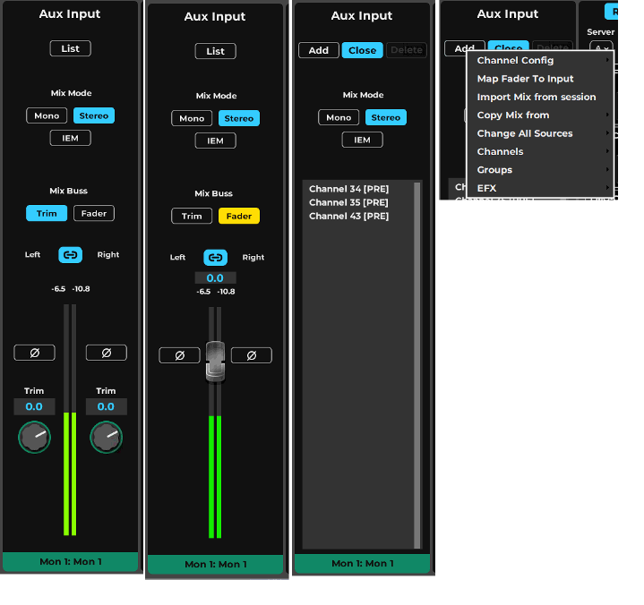
-
Input ListOpen Input List panel
-
Mix Mode SelectorSelect Mix configuration mode, between Mono, Stereo and IEM. IEM mode requires eMo-IEM license activated, enabling Immersive In-Ear Monitor mixing.
-
Mix Buss ControlBy default every input has its Trim controls that can Trim the mix buss input pre processing. Trim option provide separate left / right control if required, and is also avaiable in Input mixer Mode. Fader option uses a single fader to control the input (in relative link), when a mix buss is set to this option the correlated Mixer Fader will control the Buss Input, rather then return Output level.
-
Input Left - Right LinkLinks Left Right for all Input parameters.
-
PolaritySets Polarity Reverse, by default set to Off - no change to input polarity. When set to On, input polarity will be reversed.
-
Trim InputWhen Mix Buss is set to Trim, the Trim rotary will set the input gain trim between -inf to +10 dB.
-
Input MeterMix Buss Input Meter, can display Pre-Trim or Post Trim as set in the UI Settings.
-
Mix Buss Input FaderWhen Mix Buss is set to Fader the Input is controlled by this fader, ranging -inf to +10 dB.
-
Add Input MenuThis menu is used to add more inputs to the buss and to select global options and operations affecting all the mix buss inputs.
-
New marker
-
Input ListLists all active inputs for this Mix Buss. Each input displays its source option. to Globably set a different source use the ADD menu.
-
Add Input - Menu OptionsSelect Input options from the menu
Menu Options
Channel Config – Set Mono, Stereo, IEM. IEM requires active eMo-IEM license.
Map Fader to Input – Toggles the Mix Buss control between Trim and Fader.
Import Mix from Session – opens a browse popup to select a session, and consequently opens the Import dialog, that enables importing mix levels from the selected source.
Copy Mix From – Select a reference Mix and copy its mix levels.
Change All Sources – Set the same pick off source for all the Mix Buss inputs.
Input, FX, Monitor – Add more inputs to the mix.
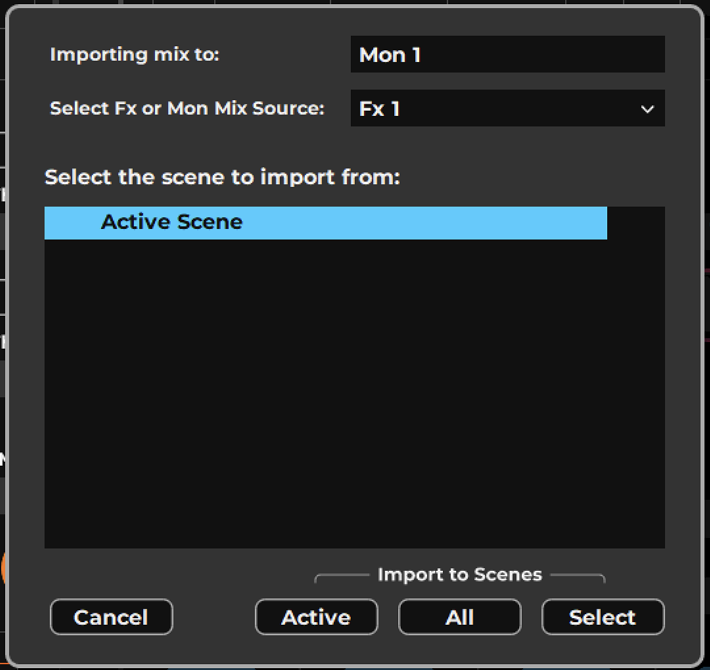
-
Import DestinationLists the mix destination, from which the import option was initiated.
-
Mix SourceSelect the mix reference source from the selected session.
-
Refernce SceneSelect the reference Scene from the session. As teh Mix may vary from scene to scene its required to provide the correct reference.
-
Cancel ImportCancells the operation
-
Import to Active SceneImport the selected Mix to the active scene in the active session.
-
Import to All ScenesImport the selected Mix to all the Scenes in teh active session.
-
Import to Selected scenesImport the Mix to seelcted scenes in the active session, a list of scenes will appear in the main section of the dialog, select the scenes to import to and confirm.
Input Section for Groups and Main Mix and Cue
Groups input section resembles Aux Mix channels with some exceptions. All inputs are latency compensated and aligned by default.
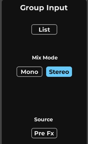
Main Mix Input provides similar control to the Aux Mix with some exceptions. All inputs are latency compensated and aligned by default.
The Cue Input list reflects the Mixer channels whose Cue/Solo buttons are activated. Deactivating a channel strip Cue button removes it from the Cue Input list.
The “Alternate Input” provides a fallback source when no Cue channels are selected.
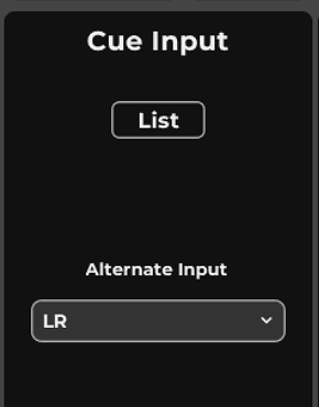
Input Section for DCA / Link
Link / DCAs control several channels together, the Input Lists all the assigned channels, however, Note that link channels are for control only, not sound. The assignmnt to the Link / DCA group can work either for DCA fader control as an offset on the channel's output gain or as a Link group for global parameter update in multiple channels from teh Mixer interface, providing the Link mode is turned on.
Matrix Input Mixer
The Matrix is used to create alternate or zone-specific mixes and to apply independent processing per zone. All mixer busses as well as individual channels, can be sent to Matrix mix, and each Matrix channel can support up to 12 channel inpus. Navigate to a Matrix channel to assign and control sources.
The Matrix Input section provides a List control that allows for selecting up to 12 mono or stereo Inputs for each of the Matrix mixers. When this limit is reached, the ADD button is disabled until one or more source busses are removed. Inputs pick off sources and mono and stereo options and their trims, are avaiable as part of the Matrix Input Mixer.
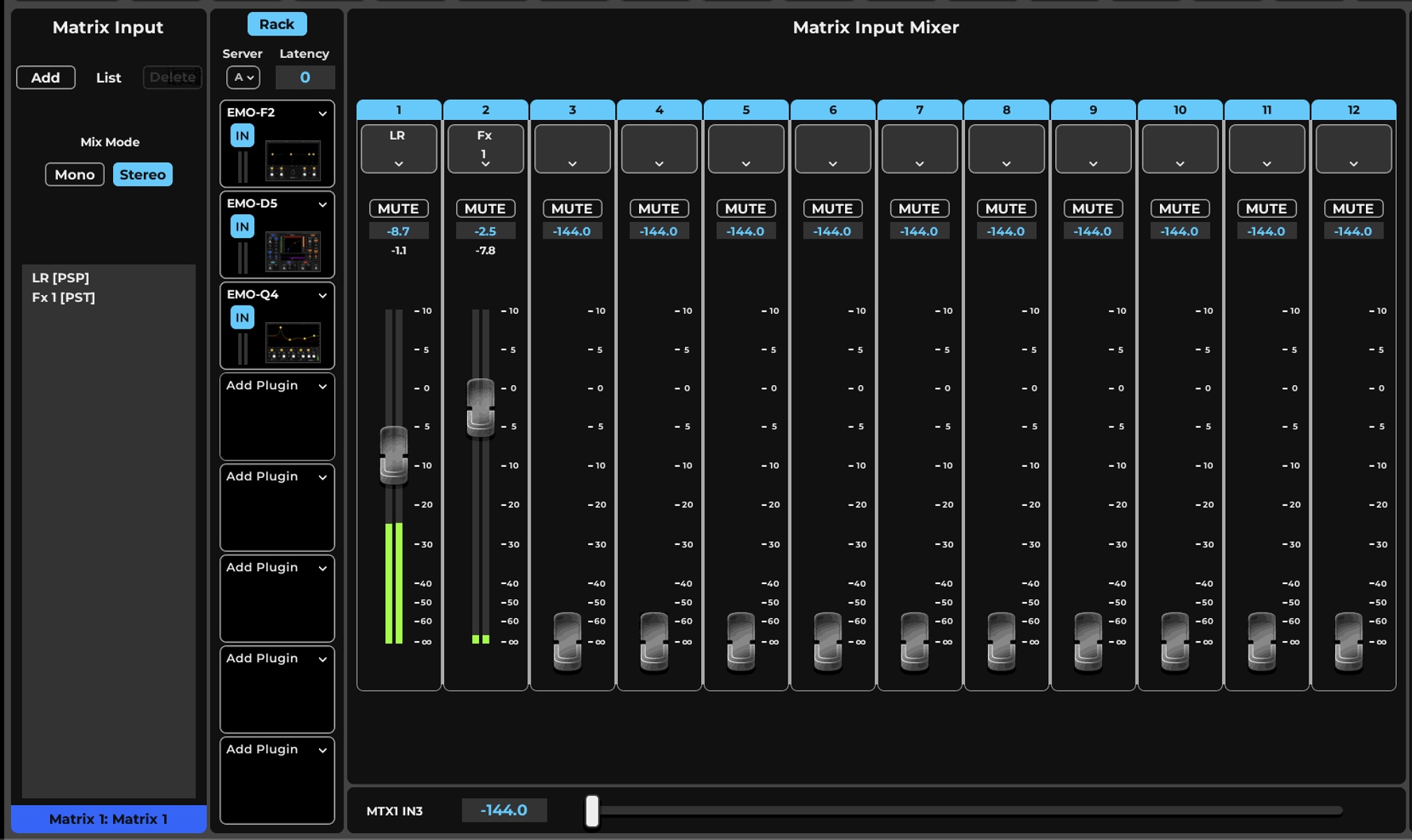
-
Input source listLists the channels and busses assigned to this Matrix channel. Up to 12 channels or busses can be assigned, and each tagged source shows its tap point. Adding inputs from this panel will add the post-pan source, further adjustments can be made in the mixer input assignmnt menus.
-
Mix ModeSelect Mono or Stereo Mix Mode.
-
Input Mixer AssignmnetsSource assignment Menus for each of the Matrix 12 inputs. Each input can be indepentely set to any pick off source point. Stereo Inputs can be assigned as stereo or as mono or summed.
-
Input Mixer Level and MuteEach Input gets an input level Fader, ranging -144 to +10 dB, a meter and Mute.
Sending Cue to Matrix
The Cue buss can be assigned to a Matrix channel. Note that in these Matrix channels, Cue is not available for audition, as this would cause a loop. By default, Cue rack latency is not reported to the Matrix. When Cue latency compensation is off, no latency is reported to the Matrix. When Cue Rack latency is set to On in the Rack menu, the Cue buss will report latency to the Matrix Mixer, which will be automatically compensated if required.
Plugin Rack
Plugins are processors that shape the sound of a channel. Some plugins tame or enhance the dynamics of a sound, while others adjust frequencies. There are plugins that control the sound within a space and others that tune a singer’s delivery. If you want to process your mix, you need plugins.
eMotion LV1 Classic ships with a wide selection of plugins. Together, they cover most live sound mixing needs. To learn more about these plugins, visit waves.com and search for the plugin by name to access its dedicated plugin page
Three plugins, eMo-F2, eMo-D5 and eMo-Q4, provide comprehensive filtering, EQ, and dynamics, are automatically inserted on the first three plugin slots of every channel and buss. These plugins together work as the channel strip main processing and will cover most of your regular mixing needs, while allowing to add more plugin processors before, after or in-between the channel's processing chain.
Plugin Rack
The Plugin Rack is a processor chainer that hosts up to eight plugins per channel. Plugins inserted in this rack are also displayed in the Rack section of the Mixer window. Signal flow is from top to bottom of the rack.
A plugin rack can be stereo or mono, depending on the channel state. If a mono-to-stereo plugin is added to a mono rack, the rack becomes stereo from that point on in the signal flow. You can drag a plugin up or down to change its position in the rack signal flow.

-
Rack On/OffRack processing On/Off. Will be turned off Automatically if the processing server is disconnected. When rack processing is off, audio still streams. If the server group assigned to the rack goes offline, the on/off button will turn red until the sever is restored or you select a different server for the rack.
-
Rack Top - Server and LatencyServer assignment menu for channel or buss; Total rack latency indicator.
-
Plugin NameDisplays the name of the plugin inserted on the rack slot. Names longer than 14 characters are abbreviated.
-
Plugin IconShows a thumbnail image of the plugin’s interface. Click to open the plugin interface.
-
Plugin Menu AccessProvides accesses (via a drop-down menu) to the plugin menu, which is used to insert and manage plugins.
-
Plugin In/OutWhen deselected (dark), plugin processing is bypassed but the plugin remains active.
-
Disabled PluginA disabled plugin remains installed in the rack but is removed from processing in the server. The plugin will no longer display an icon, but rather the text “Disabled.”
-
Recall-Safe PluginPrevents modifications during scene changes. An orange/brown SAFE notice in the rack slot indicates that the plugin is set to a recall-safe mode.
-
External InsertA rack slot can send to and receive from an external device via specified I/Os.
-
Empty Rack Slot“Add Plugin” appears in the plugin name cell.
Plugin Rack Menu
The Plugin menu is used to insert, remove, assign, and manage the selected plugin. It is also used to copy plugins and plugin parameters between racks and between rack slots. Plugin menu settings affect only the selected plugin slot.
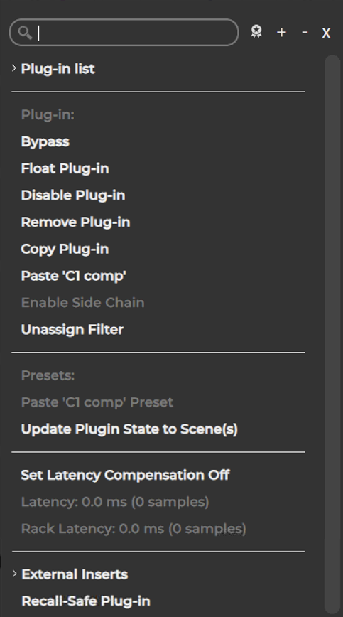
-
Serach BarSearch for a Plugin by its name. This will take directly to the plugin. Results are displayed below.
-
Plugin Menu ToolsTag - Show/Hide Unlicensed Plugins filters the displayed plugins list. Choose to see only plugins for which you have a license or all compatible Waves Plugins. + or - globally changes the hierarchy of the category lists. X closes the window without a selection.
-
Plugin List NavigatorSearch for a plugin by selecting from the list of plugins, sorted by their processing function.
-
Plugin operations
-
Sidechain ControlOnce a Sidechain Key input was assigned, it can be Enabled / Disabled from this menu, or from the plugin view top tool bar.
-
Channel Main Processing AssignAssign or UnAssign a compatible plugin to the channel Main Control section as part of the channel strip processing facility. By defualt eMo-F2, eMo-D5 and eMo-Q4 will be assigned to the Filter, Dynamics, EQ roles.
-
Paste PresetPaste a copied preset from a different instance of the same plugin.
-
Update Plugin in ScenesUpdate the Plugin parameters to one or more scenes, choosing this will overwrite the existing plugin parameters with the current settings. This applies per Plugin slot.
-
Plugin / Rack Latency SectionDisplays the Plugin latency for the plug in in the slot. Displays the Rack total latency, includding all plugins and Routing latency. Set Latency Compensation Off - for the plugin in slot. In some cases it is helpful to ignore a plugin latency, use this option with care. For some channels (like the Cue) a Rack Latency on/off option is also available. Disabling latency compensation removes the pl
-
External Insersts
-
Recall Safe PluginSets the Plugin in the slot Safe from Scene Recall, this means that it will not change its setting using the parameters data in the recalled scene, rather remain with its current settings.
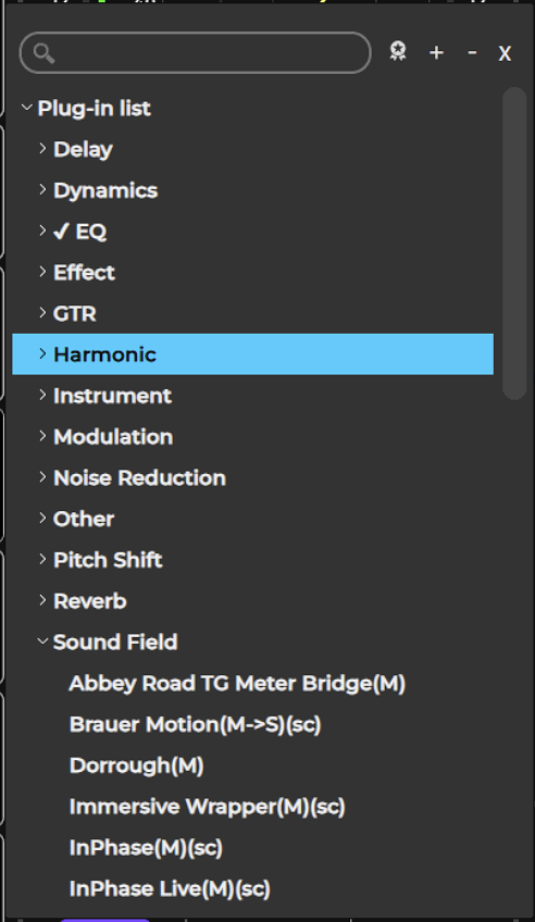
Bypass
Bypasses the plugin while keeping it in the processing chain. This serves the same function as the IN button on the rack slot.
Float Plugin
Opens the plugin user interface as a seperate floating window. This is the same action as clicking the undock button in the plugin view tool bar.
Once a plugin is floated, it can be Pinned to stay in that window when selecting another plugin to float. Its advised to place floating plugins on a separate screen, as these windows are always-on-top and may hide LV1 UI.
Disable Plugin
Removes the plugin from the processing chain without deleting it from the rack. Disabling a plugin removes its latency from the rack. It also frees up processing power. You can re-enable the plugin without losing its settings, controls, or automation assignments. When a plugin is disabled, its name will remain visible above the slot and its icon will be replaced with DISABLED. You can also disable and enable a plugin by clicking its rack slot while holding down the Control key.
Remove Plugin
Deletes the plugin from the rack slot. All parameter settings and control assignments are lost.
Adding, removing, disabling, or moving a plugin changes the structure of the rack, which may result in a brief audio mute. Do not make these changes when an audio interruption is unacceptable.
Wait until there is a pause in the performance.
Copy
Copies the plugin and its parameters. This enables pasting the plugin and its current settings to another rack slot. There are two paste options: Paste [plugin name] and Paste [plugin name] Preset.
Paste [plugin name]
Pastes the copied plugin and its parameters to an empty slot or replaces the plugin that occupies the slot. In certain circumstances it is possible to paste a preset into an existing plugin. (See Paste [plugin name] Preset below.)
Update Plugin State to Scene(s)
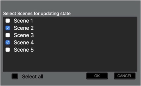
Updates the current plugin’s settings in selected scenes. Choose the scene(s) you want to update.
External Inserts
You can add external inserts to a plugin rack. An external insert follows the same routing path as plugins and can be moved up or down the rack to change its position in the processing chain.
Follow these steps to add external inserts:
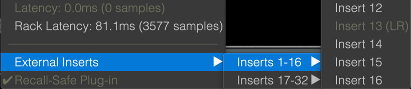
- Choose a rack slot.
- Select External Inserts from the Plugin Menu.
- Choose an available insert from the menu. This opens the External Insert control page.
- Select physical send and return I/Os using the drop-down menus.
- Rename the insert using the Device cell, if desired. Use the Insert drop-down menu to move between inserts.
If no send is assigned, then the insert will be bypassed. It remains in the rack and its place in the processing chain is unchanged. If no return is assigned, then any other source assigned to this insert return will be heard.
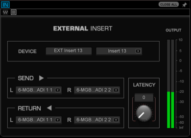
A mono/stereo full-scale meter shows the level of the return signal This helps to maintain proper levels on sends and returns.
The Latency knob is used to adjust the amount of delay to and from the external insert device. Unlike a plugin, an external insert doesn’t declare its delay to the plugin-buss latency compensation engine, so this must be done manually.
For more information, please refer to www.Waves.com/support.
External Insert Latency Calculation
The latency of an external insert is determined by its path, which depends on the type of processing being performed. The diagrams below illustrate how latency is calculated in three different situations.
1: Processing with an External Device An external insert is sent to and from an external device, via one or more SoundGrid I/O devices.

Stereo and Mono Plugins
- Adding or pasting a mono plugin module to a stereo channel converts the plugin to stereo. The mono plugin’s parameters will usually be applied to both sides of the stereo plugin.
- If a stereo plugin is added to a mono channel, the settings of the left stereo channel become the mono parameters. The two-channel parameters will be restored if the plugin is returned to a stereo channel.
- Adding a mono-to-stereo plugin to a mono rack converts the rack to stereo from that point downward..
Plugin User Interface
This view displays a plugin’s standard user interface in a floating window and shows all plugin controls. Certain plugin interface graphics have been modified to fit the Plugin user interface.
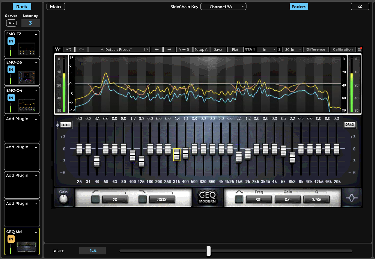
-
Sidechain source menuA drop-down menu at the top of the plugin user interface assigns a sidechain source to the selected plugin; choosing a valid sidechain activates the plugin's sidechain functionality. Sidechain assignments are specific to each plugin, not the channel.
-
Back to Main ControlClose the Plugin interface view and go Back to the Channel Main Control section.
-
UnDock PluginUndock the Plugin from the Channel Plugin view to an independent Floating window. The Floating window can be placed in any available screen and can be pinned to stay in place. Floating plugin position is saved in the Scene and Session.
-
GEQ to FadersMap the GEQ plugin to the Fader Bank faders, this is turned on automatically for the first GEQ in a rack. Set teh Fader Bank to Edit mode to control GEQ with the tactile faders. When this mode is active GEQ can also be controlled from the Tablet App MyFOH.
-
Plugin ThumbnailTo open the plugin user interface, click on its plugin icon in the rack.
Controlling Plugin Parameters
LV1 Rack supports hundreds of plugins for various type of processing, from EQ and Dynamics to Reverb and Delay Effects, to Saturation and Modulation, to problem solvers and pitch correction and feedback suppression. Every plugin has some unique workflow in its interface, that makes using it easier and get to the point quicker. The most immediate control for these plugins is by using the large touchscreen interface and directly accessing the pliugin parameters.
In addition to the touchscreen the tactile faderbank with its encoder and faders can be usful for many hands on tasks.
Fader Bank
Touch & Turn
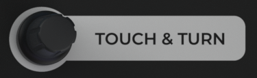
For immediate control of a specific assigned plugin, use the Touch & Turn knob. Select a control—whether with the touchscreen or fader bank—and turn the knob to adjust. You can instantly move the mapping from one control to another.
Encoders - Edit Parametrs
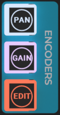
Select the “Edit” on the encoder panel. The Channel will be auto-mapped to the Fader Bank 16 Encoders, with the Main controls of the Channel Strip aggregating the mapped Filters, Dynamic and EQ plugins, more on this in the next chapter.
While in Channel Edit mode - Knob 15 'Rack' - will take you to detailed mapping of teh plugin in teh Rack. Choosing this mode will start with a plugin select page, once seelcted, this maps each encoder to a parameter control on the plugin, which can be a variable control or a two-step switch. The control name and value appear in the channel’s scribble strip.
Controls are organized in layers of twelve:
Encoders | Function |
|---|---|
Encoder 1-12 | Encoder 1–12, page 1 Mapped to the first twelve controls on the plugin interface. Encoder 1–12, page 2 Mapped to the next twelve controls. |
Encoder 13 | Returns you to the Main Control Section. |
Encoders 14/15 | Previous page/next page. |
Encoder 16 | Bypasses the Rack selector and Main mapping. |
Touchscreen
Touch Screen
Use the touchscreen to directly adjust controls in assigned plugins. Click on a control and slide the Touch & Slide control at the bottom of the window for quick, precise adjustment.
Floating Plugin User Interfaces
Floating Plugin User Interfaces
You can undock the plugin interface and position it anywhere on your display.
Click the Expand button in the upper-right corner to undock the window. When another plugin interface is undocked, it becomes the front-most window. Click on a plugin’s icon in the rack to bring its floating interface to the front.

Controls for the frame are at the top of the window.
IN | Plugin bypass |
SC menu | Select SC source assignment |
SC | Sidechain in/out |
Close All | Closes all floating windows |
PIN | Keeps the window in front of all other windows |
Close a floating window to return the plugin interface to its docked position. Up to five windows can be opened simultaneously.
Floating plugin window preferences (dock/undock and window location) are saved with scenes. Window settings are also part of a session. Floating windows recall safe and scope status and are set in the Show window.
Click “Back to Main” to return to the Main Control section.
Main Control Section
The Main Control Section enables you to view and control important plugin parameters. A compatible dynamics processor, a multiband EQ, and an HP/LP filter can be assigned to these controls. This is the primary mixer section for sending channels and busses to Aux channels. Send level, send source, and pan/rotation are controlled here. Controls in the Main Control Section map to the fader bank set to Edit mode to provide quick access to the most used parameters such as Dynamics thresholds and EQ gain and frequency, further it enables mapping for individual plugins and all Aux sends options.
If you are in a plugin user window, click on the Back to Main button to open the Main Control Section.
Set encoder mode to EDIT in order to access the selected channel quick controls.
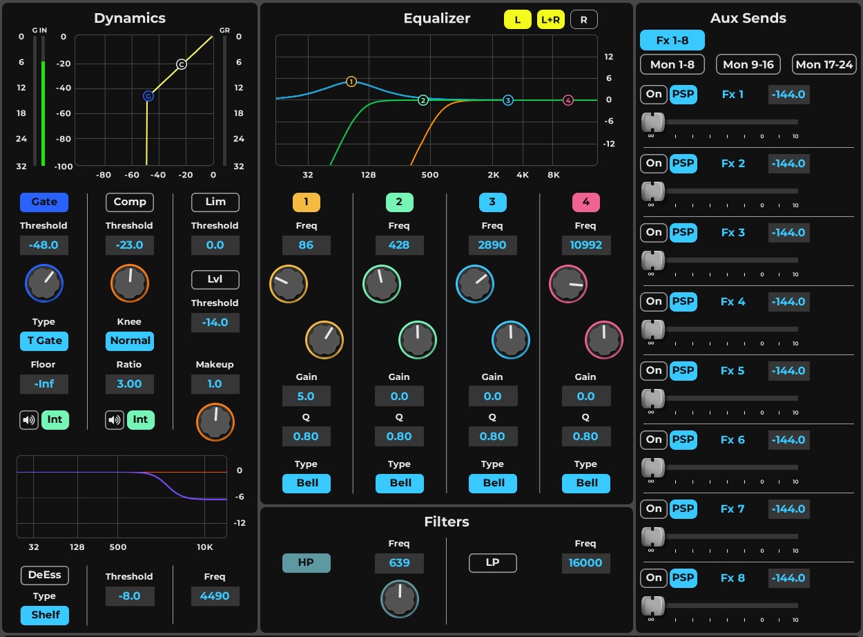
-
DynamicsThe Dynamics zone provides control over each section of an assigned dynamics plugin processor, with parameters such as threshold, ratio, and makeup mapped to dedicated controls.
-
Equalizer and FilterAssigned EQ and Filter plugins controls are mapped to this Equalizer zone of the Main Control section; the mapping may vary from one EQ plugin to another.
-
Aux SendsThe Aux Sends zone is the primary mixer area for sending channels and busses to Aux channels; send level, send source, and pan/rotation are controlled here.
Dynamics Mapping in the Main Control Section
The Main Control section provides control over each section of a dynamics plugin processor. Threshold, ratio, makeup, and other critical parameters are mapped to dedicated controls. Additional processing adjustments can be made in the plugin user interface. The display and controls vary by plugin. The example below shows an eMo D5 Dynamics processor mapped to the Main Control section.
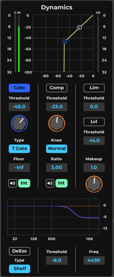
-
GATEThe Gate section of the dynamics processor mapped to the Main Control section, with a dedicated threshold control. It is one of up to six dynamics plugin sections available in the Main Control section.
-
COMPThe Compressor section of the dynamics processor, with dedicated threshold and ratio controls mapped to the Main Control section. Critical parameters such as ratio are mapped to dedicated controls.
-
LIMThe Limiter section of the dynamics processor, with a dedicated threshold control mapped to the Main Control section. One of up to six dynamics plugin sections mapped here.
-
LVLThe Level section of the dynamics processor, with a dedicated threshold control. It is one of the up to six dynamics plugin sections mapped to the Main Control section.
-
DeESSERThe De-Esser section of the dynamics processor mapped to the Main Control section, with a dedicated threshold control. One of up to six dynamics plugin sections mapped here.
-
MAKEUPMakeup gain is one of the critical dynamics parameters mapped to a dedicated control in the Main Control section.
Dynamics Plugin Controls
While the Main Control page provide quick acess to the main parameters, The eMo-D5 plugin user interface can be accessed for more controls and options over each process function.
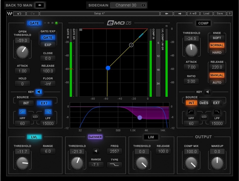
-
Back to MainFrom a plugin user window, click the Back to Main button to return to the Main Control Section.
-
GATEThe Gate section in the dynamics plugin user interface. Its threshold and related parameters are mapped to dedicated controls in the Main Control section, while additional adjustments are made here in the plugin UI.
-
COMPThe Compressor section in the dynamics plugin user interface, with threshold and ratio among the critical parameters mapped to dedicated controls in the Main Control section.
-
LVLThe Level section in the dynamics plugin user interface, one of up to six dynamics plugin sections mapped to the Main Control section.
-
DeESSERThe De-Esser section in the dynamics plugin user interface, one of up to six dynamics plugin sections mapped to the Main Control section.
-
LIMThe Limiter section in the dynamics plugin user interface, with its threshold mapped to a dedicated control in the Main Control section.
-
OUTPUT (Makeup)The Output section of the dynamics plugin, including the Makeup gain that is mapped to a dedicated control in the Main Control section.
EQ and Filter Controls in the Main Control Section
Assigned EQ and Filter plugins controls are mapped to the Main Control section. Mapping may vary from one EQ plugin to another.
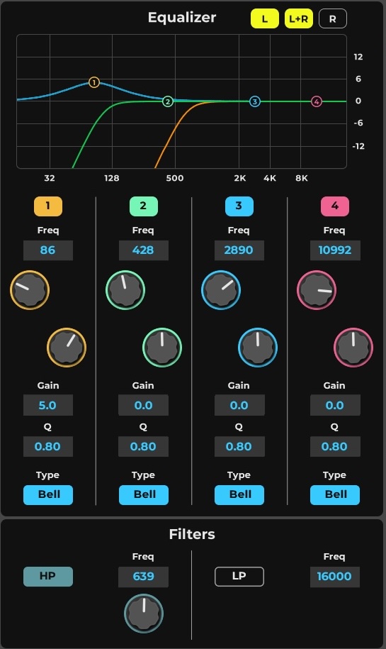
-
EQ Band On/Off
-
EQ Band FrequencyFor most mapped EQs the range will be 20Hz-20Khz
-
EQ Band GainFor most mapped EQs the range will be +/- 18dB.
-
EQ band Q factorSets the filter Q factor, affecting bell width and filters resonance. Q can also be set with a pinch gesture on the graph band.
-
EQ band TypeSets the EQ band filter type, ranging from bell to shelf.
-
Filter HiPassSet the HPF on/off and cutoff frequency,
-
Filter LoPassSet the LPF on/off and cutoff frequency,
-
Stereo ControlSelect Stereo control options for both EQ and Filter, control Left side or Right side or/and Link between them. When linked parameters can preserve relative offsets if such were set before linking.
-
GraphThe Graph displays the L/R EQ Curves, the L/R Filter curves and provides graph markers control for on screen control of the EQ bands.
EQ Plugin Controls
Assigned Plugin can be mapped in detail from the Plugin interface.
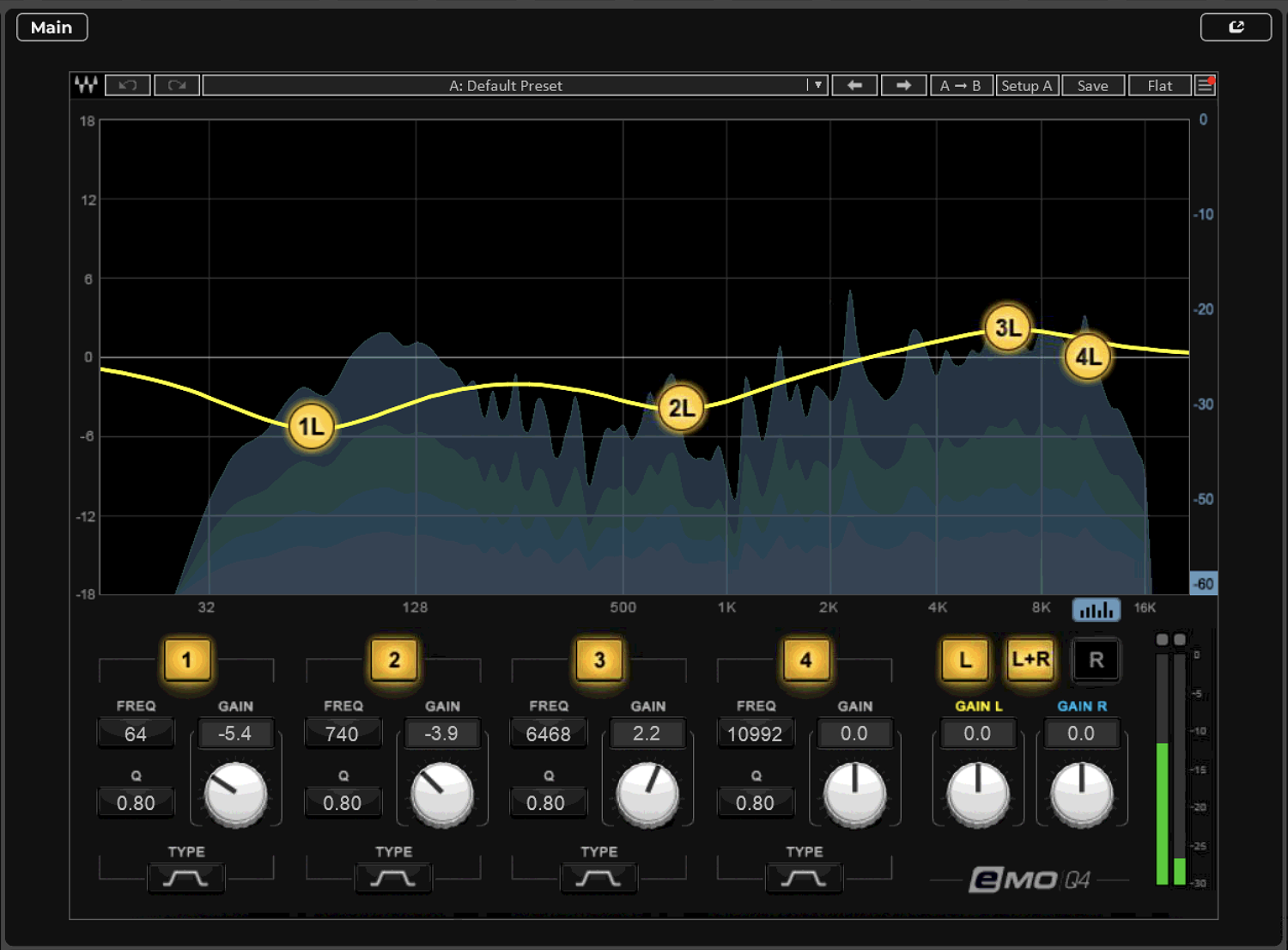
-
EQ GraphDisplays the output Curve created by the 4 Bands. 4 Markers provide per band graphic control over gain, frequency and Q (Pinch). The Graph can display RTA when selected.
-
New marker
-
4 Bands ControlsPer Band controls, on/off, Frequency, Gain, Q and Type.
-
Stereo ControlSelect Stereo control, Right, Left and Link.
-
OutputControl output Gains and Meters display.
Filter Plugin Controls
An assigned filter is controlled from the Channel window EQ section. In this example, an eMo F2 filter is mapped to the Input section and its graphic display is shown in the Main Control section. Mapping and graphics vary among plugins.
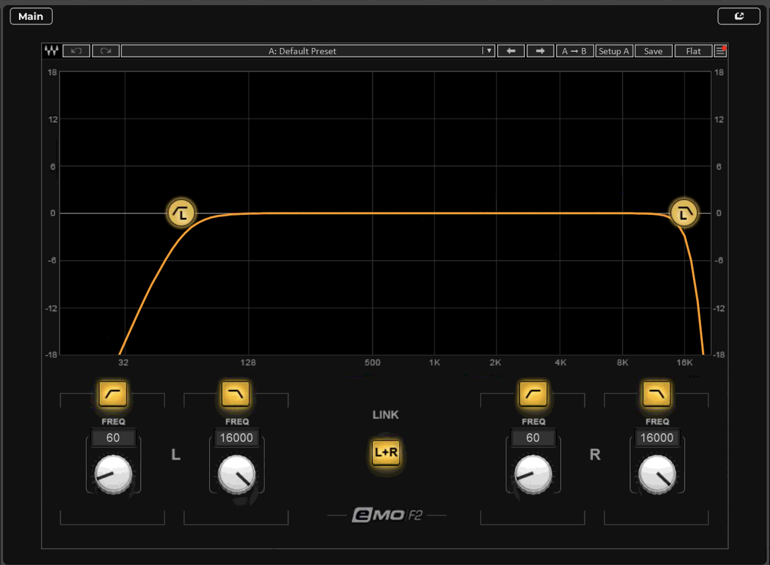
-
Filter graphic displayThe Main section graphic filter display. Channels are displayed together or separately, depending on the plugin and the Link setting.
-
Left HP/LP frequencyLeft-channel high- and low-pass filter frequency controllers in the Input section. The high- and low-pass filters can be engaged/disengaged individually and controlled separately; filter range depends on the assigned plugin.
-
LINKFilter Channel Link links the left and right channels in the Channel Input section. When Link is on, both channels move in tandem and any offset between left and right is maintained.
-
Right HP/LP frequencyRight-channel high- and low-pass filter frequency controllers in the Input section. The filters can be engaged/disengaged individually and controlled separately, with range depending on the assigned plugin.
Assigning a Plugin to the Main Controls
Plugin assignments are made in the Plugin menu. If a plugin is already assigned to a set of controls, the menu item will display Unassign [category]. If no plugin is assigned, you can select Assign [category].

One plugin from each category (filter, EQ, dynamics) can be assigned at the same time:
- A plugin will be assigned automatically if no other plugin of its category is present in the rack.
- Assigning a new plugin will replace the existing plugin in that category.
- Unassigning a plugin does not affect its processing status. It can always be controlled from its Plugin user interface. Consult the Waves website for a current list of assignable plugins.
Assigned plugins can be controlled in several ways:
- Filters are controlled at the bottom of the main EQ section
- EQ and dynamics processors are controlled in the Channel Main Control section.
- All Main section controls are available in the Mixer Channel Focus Mode
- Fader Bank mapping per selected channel when encoder are set to EDIT
Sections of filters, EQ, and dynamics processors can be switched on and off from the Mixer window (DYN/EQ Channel Strip mode). These assignments are also mapped to external control surfaces.
AUX - FX/Mon Sends Section
The Aux Sends section is used to send a channel’s signal to an auxiliary buss while providing a dedicated set of gain and pan controls for that specific route. This is independent of the channel’s main output and pan. These auxiliary busses converge in Aux channels, which can serve many functions, such as effects or monitor mixes.
- When using an aux for effects processing, the effect plugin is placed in the Aux channel, which is then routed back to the main out or sent to other destinations.
- When using an aux for monitoring, the Aux channel is assigned directly to an I/O that feeds the monitor.
In both cases, each source channel sent to an aux buss can have its own gain and pan settings. Aux channels are controlled in the AUX layer of the Mixer window.
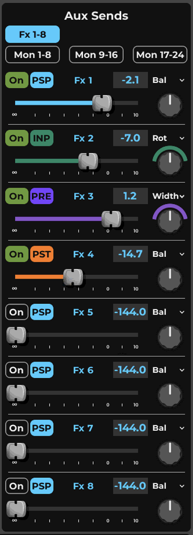
-
Aux Sends SelectPages correlated with Mixer configuration options
-
Send On/OffSend will turn on automatically if fader is moved from -144.
-
Send Source SelectSelect available pick off point sources: INP - input pre process, PRE - pre fader post process, PST - post fader, PSP - post fader post pan.
-
Aux Channel Name and Value DisplayDisplays the name of the Aux channel by default. When an aux send fader is touched, its value is displayed in the box until the control is released. Similarly, the aux send pan/balance/rotate value is displayed when its control is touched
-
Pan ControlPan knob and Pan options menu. For stereo source to stereo destination the Pan Menu provides extensive panning options - rotation, width and independent L/R panning, as well as L/R swap.
-
Channel Send FaderSend level from -144 to +10 dB. Aux faders are color-coded to match the INP/PRE/PST/PSP source selection.
Input Channel, Groups and FX/Monitor auxiliaries can send to the Aux FX/Monitor busses, with some exceptions, The Aux FX/Monitor can only send to a Aux bus with a greater index. Group Mix busses can be set to Post FX.
eMo Immersive In-Ear Monitoring
Aux busses can work in IEM mode, which uses eMo IEM to create an immersive mix for In-Ear Monitors. This results in a monitoring experience that is more comfortable for most musicians, especially after long exposure. eMo is intended for Aux Mon channels. The mode can be activated in the Aux Channel window or Mixer window.
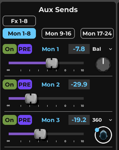
IEM immersive monitoring is indicated by the “head” icon in the sends section of the AUX channel. The green dot indicates the orientation of immersive panning.
eMo IEM requires a separate license. The software must be installed and activated to be available to LV1 and Mobile apps. Use Waves Central to purchase and manage all Waves software products.
Fader Bank Channel Edit
When the Fader Bank encoders are set to Edit mode, they will automatically map the most important main controls of the selected channel to the encoder set.

Channel Edit Mapping Table
Channel Page | Knob | Label | Rotary Value | Rotary Function | Toggle Function | Knob Highlight Color |
|---|---|---|---|---|---|---|
Default page (1) | 1 | Preamp/Trim | Gain dB | Gain | None | Green |
2 | HP | Freq Hz | Hi Pass Filter | HP On/Off | Dark Cyan | |
3 | Gate | dBFS | Gate Threshold | Gate On/Off | Deep Blue | |
4 | Comp | dBFS | Comp Threshold | Comp On/Off | Orange | |
5 | MakeUp | Gain dB | Comp make up gain | None | Orange | |
6 | EQ 1 Frq | Freq Hz | EQ Band 1 Frequency | EQ Band 1 on/off | Yellow | |
7 | EQ 1 Gn | Gain dB | EQ Band 1 Gain | EQ Band 1 Filter type | Yellow | |
8 | EQ 2 Frq | Freq Hz | EQ Band 2 Frequency | EQ Band 2 on/off | Turquoize | |
9 | EQ 2 Gn | Gain dB | EQ Band 2 Gain | EQ Band 2 Filter type | Turquoize | |
10 | EQ 3 Frq | Freq Hz | EQ Band 3 Frequency | EQ Band 3 on/off | Blue | |
11 | EQ 3 Gn | Gain dB | EQ Band 3 Gain | EQ Band 3 Filter type | Blue | |
12 | EQ 4 Frq | Freq Hz | EQ Band 4 Frequency | EQ Band 4 on/off | Pink | |
13 | EQ 4 Gn | Gain dB | EQ Band 4 Gain | EQ Band 4 Filter type | Pink | |
14 | Pan | Deg | Panning | Panner Type | White | |
15 | Rack | Goto Rack page | Gray | |||
16 | Aux | Goto Aux page | Gray | |||
Rack Select poage | 1 | 1 "Plugin name" | Select plugin to map | |||
2 | 2 "Plugin name" | Select plugin to map | ||||
3 | 3 "Plugin name" | Select plugin to map | ||||
4 | 4 "Plugin name" | Select plugin to map | ||||
5 | 5 "Plugin name" | Select plugin to map | ||||
6 | 6 "Plugin name" | Select plugin to map | ||||
7 | 7 "Plugin name" | Select plugin to map | ||||
8 | 8 "Plugin name" | Select plugin to map | ||||
9 | ||||||
10 | ||||||
11 | ||||||
12 | ||||||
13 | Rack On | Rack On/off | ||||
14 | Prev Page | toggle page | ||||
15 | Next Page | toggle page | ||||
16 | Main | back to main mapping / GUI | ||||
Plugin Mapping pages dependent on Plugin | 1 | Plugin | Plugin | |||
2 | Plugin | Plugin | ||||
3 | Plugin | Plugin | ||||
4 | Plugin | Plugin | ||||
5 | Plugin | Plugin | ||||
6 | Plugin | Plugin | ||||
7 | Plugin | Plugin | ||||
8 | Plugin | Plugin | ||||
9 | Plugin | Plugin | ||||
10 | Plugin | Plugin | ||||
11 | Plugin | Plugin | ||||
12 | Plugin | Plugin | ||||
13 | Rack On | Rack On/off | ||||
14 | Prev Page | toggle page | ||||
15 | Next Page | toggle page | ||||
16 | Main | back to main mapping / GUI | ||||
Aux Pages | 1 | Aux 1 | Send Level | Send On/Off | ||
2 | Aux 2 | Send Level | Send On/Off | |||
3 | Aux 3 | Send Level | Send On/Off | |||
4 | Aux 4 | Send Level | Send On/Off | |||
5 | Aux 5 | Send Level | Send On/Off | |||
6 | Aux 6 | Send Level | Send On/Off | |||
7 | Aux 7 | Send Level | Send On/Off | |||
8 | Aux 8 | Send Level | Send On/Off | |||
9 | Reservedd | |||||
10 | Aux 1-8 | |||||
11 | Aux 9-16 | |||||
12 | Aux 17-24 | |||||
13 | Aux 25-32 | |||||
14 | Aux 33-40 | |||||
15 | Aux 41-48 | |||||
16 | Main | back to main mapping / GUI |
Cue Settings
The Cue function enables auditioning/monitoring of a channel or buss. When the Cue/Solo button is pressed on a channel or buss, that source is sent to the cue buss, which can then be sent to an I/O for monitoring. When Cue is not pressed on any channel, the cue buss takes its input from an alternate source, typically the main buss. A muted channel will still send its signal to the cue bus.
The Cue channel provides all the functions of other mix busses, including a plugin rack. Its output is typically connected to the operator’s headphones or monitors.
Cue Controls
The Cue control panel is located in the Channel window. To access this page, click the Gear icon under the Clear Solo button on the Top Bar.
The Cue control panel consists of six sections.
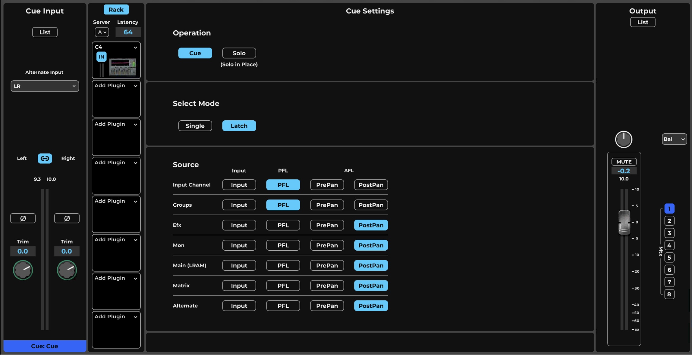
-
Input Section
-
Cue Rack
-
Solo / Cue Mode
-
Select mode
-
Source Selection
-
Output Section
Input section
- Open List: Opens the cue channel assignment panel. Any mixer channel or buss with an active Cue button appears in this list. Assignments can also be made from the Input List. Click Add to open a drop-down menu for input assignments.
- Alternate Input: Serves as a fallback input to the Cue buss when no other busses are assigned. Any channel or buss can be selected as the alternate input. The default assignment is Main L/R.
- Cue channel Input Trim, meter, and phase polarity reverse: Controls the level and phase of the Cue buss input.
- Input Channel Assignments: Used to assign busses to the Cue channel. The Input source (INP, PRE, PST, PSP) is shown next to the assigned buss. Assignments can be made in this panel or on the Mixer window channel strips.
Cue Plugins Rack
The Cue plugins rack can hold up to eight plugins. There is no Main Control Section on the Cue Channel page; plugins are controlled directly from the plugin user interface. Refer to Channel Window > Plugin Rack Section to learn more about using the plugins rack.
Cue/Solo mode select
Toggles between Cue and Solo-in-Place modes.
Cue Mode: The cue signal is sent to the Cue buss for monitoring. Main mix outs are not affected.
Solo-in-Place Mode (Cue button becomes Solo button): Setting a channel to Solo-in-Place will mute all other tracks when the Solo button is pressed. Tracks that are fed by the soloed channel, or those used as sources for the soloed channel will not be muted. Default: Cue.
Select Mode
In Single mode, only one channel at a time will be in a cue or solo state. Latch mode allows multiple selections. Click the button once again to deselect it.
Source Selection
Selects cue source send points. Each channel category (input channels, groups, aux, etc.) can be assigned specific sources, and all member channels of that type will exhibit the same source behavior.
Options include: Input, PFL, AFL pre-pan, AFL post-pan.
Output section
Configures cue output assignments in the same manner as channel direct outputs on any channel. Select Open List and add output assignments. This section includes fader, pan/balance/rotate control, and mute, as well as direct output assignments. The Cue buss can also be sent to a Matrix channel.
Talkback Settings
The Talkback function sends the signal of an assigned I/O to selected busses, which are then routed to I/Os. Talkback is used primarily to communicate between the operator and the artists or staff. It can also be used to distribute a reference signal for calibration or to check that stage equipment is working properly. Click the Gear icon under the Talk button on the Top Bar to access the Talkback channel page. This button is not latching.
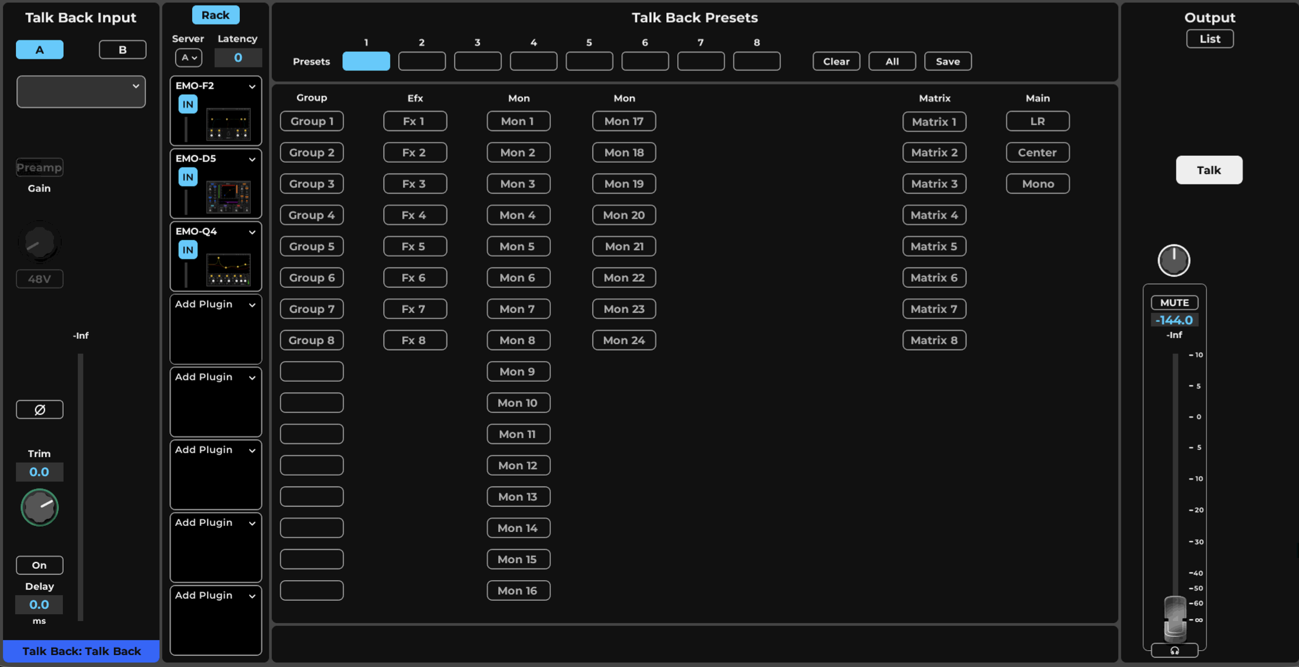
-
Input Preamp sectionThe Input section of the Talkback channel patches to any hardware or software I/O that’s assigned to the mixer. It can control preamp analog level, 48V phantom power, and phase in the same manner as Input channels. The Input section includes input meters and peak value indicators, as well as input trim controls, assigned filter adjustment, and delay control.
-
ALLSelecting All patches Talkback to every buss in the routing grid.
-
Routing presets 1-8This grid is used to determine which busses (Groups, FX, Mon, Matrix, Main Outs) the Talkback channel is patched to. The name of the buss is reflected in the corresponding button on the interface when you rename a buss. Its abbreviated name appears on the button. Selecting All patches Talkback to every buss. Up to eight Talkback routing configurations can be saved and recalled as presets. Select
-
SAVESaves the current Talkback routing configuration as one of up to eight presets.
-
Route to BussesSelects which busses the Talkback channel is patched to in the routing grid.
-
CLEARThe Clear button removes all patches visible on the grid. It does not affect saved presets.
-
Pan / BalancePan/balance/rotate control in the Talkback Output fader section.
-
MUTEMute control in the Talkback Output fader section.
-
Output faderFader for the Talkback Output section, which routes the Talkback buss to assigned I/Os and busses. The Talkback buss can be routed to any available I/O. It can also be routed to mixer busses, including Main outs. The Output section of the Talkback page is identical to that of the Cue channel. Select Open List and add output assignments. A fader Section includes fader, pan/balance/rotate control, m
-
TALKNon-latching Talk switch that activates Talkback; it must be held open to talk and is not latching.
-
Plugin RackThe Talkback channel accepts up to eight plugins. There is no Main Control section on this Channel page, so plugins are controlled directly on the plugin user interface. Refer to the Channel > Rack section to learn more about using the plugins rack.
Top Bar Talk Control
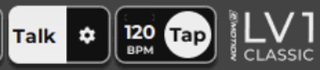
Talkback is activated with the non-latching Talk switch. It must be held open to talk. When Talkback is On, the top part of the button is blue. Click the Gear icon below TALK to directly access the Talkback channel page from any window.
Talkback On/Off can also be mapped to a control surface or assigned to user-assignable keys, which are set up in the U/I Settings window (Setup > U/I Settings > User-Assignable Keys).
Using Talkback to distribute a test signal
Since Talkback can be sent to any I/O or buss, it is a convenient way to broadcast a reference tone or other test signal. Insert a signal generator into the Talkback plugins rack. This signal will be distributed to all selected busses and I/Os.
Link / DCA Controls
The Link / DCA groups in LV1 provide two multi-channel control options. The first one is 'Link' which is about using one channle's parameter control to affect multiple channels with the same parameter. For example, changing Gain in one channel will change gain in multiple channels as they are Linked.
The second is DCA which is a 'remote control' gain fader that offsets multiple channel's output fader by its value.
We use the same group assignment for these two functions, where DCA fader is always available, and Link can be activated on demand per Mixer window.
Link
Links allow for global control of fader levels and other mixer parameters across multiple channels. When channels are assigned to a link group, their controls move together. Changing one control automatically adjusts the corresponding controls of the other channels in the group. Existing offsets are maintained but can be changed.
The mixer supports 16 link groups, and a mixer channel can be assigned to any number of these groups. There is no limit to the number of channels that can be assigned to a link. Link assignments are made in the output section of the Channel window, Mixer Route and Channel Focus Modes, and in the Link input section. Any mixer channel can be assigned to a link, except for Cue and Talkback.
The Link button is in the upper left corner of the Mixer window. When Link is on, activated links are identified by small numbers next to the Channel strip Name.
Linked parameters can only be controlled from Mixer windows.
A drop-down menu allows you to select which link group will be used. A channel that is a member of more than one link group uses only the currently selected link. The Spill button displays all channels in the selected link.
Link button behavior
Only the selected link group is active. Deselecting the Link button disables all link groups. This action affects only links and does not impact DCAs. A DCA remains active regardless of the link group selection or the status of the Link button.
Links and DCAs are discussed in detail in the Mixer chapter of this user guide.
DCAs
A DCA is a tool for remotely controlling the trim values of a group of faders. A DCA is not an audio path like a group buss. Rather, it is a fader that trims other faders assigned to it. This concept is a development that originates from classic mixer VCAs.
When a DCA fader is moved, the controlled faders do not move; they stay in their original positions.
Ghost faders indicate the current level of each channel, reflecting the offset introduced by the DCA fader. So, if the DCA fader remains at zero, it has no effect on the controlled fader and the channel gain remains unchanged.
A DCA fader move of +5 dB (for example) will result in a corresponding +5 dB change in the position of the ghost faders. Still, the channel fader itself does not move. In this example, channels 3 and 4 are assigned to Link Group 1, so their levels change along with that Link fader. Channels 1 and 2 are not members of Link group 1, so they are not affected. DCAs are defined using the Link Group assignments buttons in the Channel window output section or the Internal section of the Patch window.
Output Section
A channel can output to any of the main outputs and to all available I/Os. It can be assigned to mix groups, mute groups, matrix, and Link/DCAs. I/O properties, such as signal source, trim, and delay group assignment are set here. Output sections are similar for Input channels and mix buss channels, the difference is only in avaible internal destinations.
The Output section is divided to two main parts, the first part is internal routing buttons array with the Fader Pan/Mute section, and the second is the IO assignments list with its per output settings.
Output Assignments
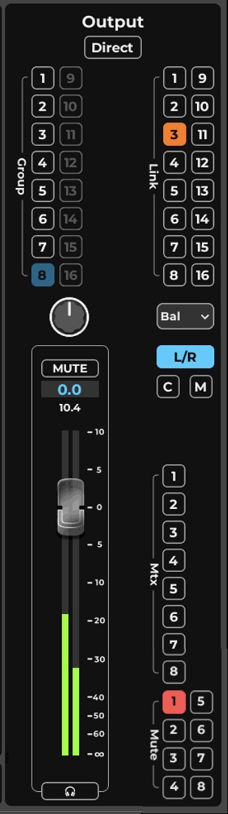
-
GroupAssigns the channel to mix groups. The route will use the PST/PSP output of the channel depending on the destination mode. All Input channels can be assigned to Group mix busses, a group can send to another group with higher index. In a group is set to be post FX, than any FX can output to that group.
-
Mute AssignmnetAssigns the channel to mute groups. any channel and mix can be assigned to mute groups.
-
Direct - Output ListToggles the channel Direct Output panel view, which assigns I/Os to the channel's outputs.
-
MtxAssigns the channel to the matrix busses. Any channel and mix can be assigned to matrix, however each matrix can take up to 12 inputs, when the limit is exceeded routing to that matrix will be disabled. Source pick off point can be selected in teh Matrix Input Mixer.
-
LinkAssigns the channel to Link/DCAs for global control and DCA fader control.
-
PannerEvery channel that outputs to a stereo destination will have a Panner, a mono channel will have a -3dB panning law, a stereo channel will have a Balance control by default and using the panner menu more panning option are available, such as Rotation - preserving the image of the stereo source, Width controlling the stereo image, individual L/R panning and a flip L/R option.
-
Main RouteAssigns the channel to the Main mix busses. Any channel except for Matrix and Cue can be assigned to the Main mix.
-
MuteMutes the channel outputs. Unless set differently in the Mxier settings, all the channels destinations will be muted except for the Cue.
-
Fader / MeterChannel output gain is controlled by the Fader its value is displayed in the dedicted value box, ranging -144 to +10 dB. The Meter underlaying the Fader displays the output levels from -144 to +10 dB, peak values are displayed in the dedicated value box.
-
Cue / SoloCue sends the channel to the Cue buss for auditioning, this route will send it output even if the channel is muted. The source for Cue auditioning is set in the Cue settings panel. When set to Solo, Input and Groups channels can be set to Solo, which will mute all other channels leaving only the Solo channels feeding the Main mix. Use the Top-Bar 'Clear Solo' to clear Cue and Solo routing from all
Direct Output List Section
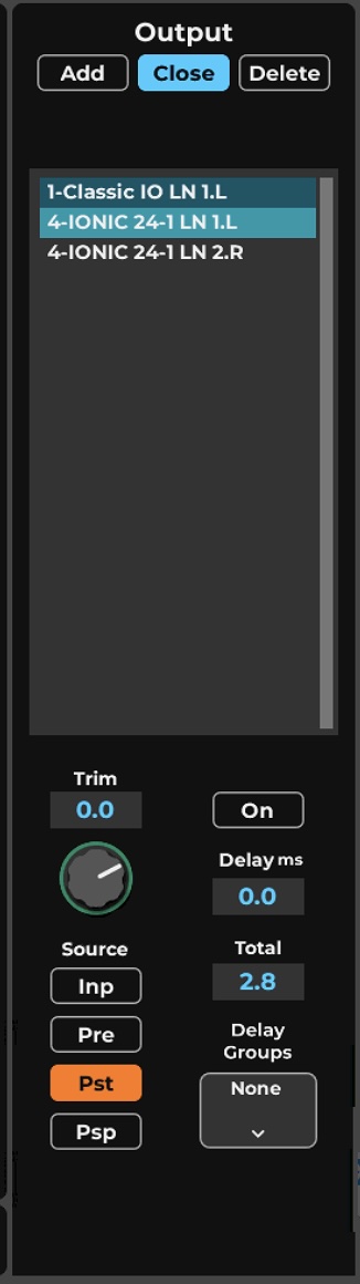
-
Add Assignment MenuSelect the IO destination outputs
-
Close / Direct ListToggle IO assignment Direct Output List panel to view and back to Internal Outputs.
-
DeleteDelete selected output assignmnts.
-
IO Assignments ListDisplays the Output IO destinations assigned to this channel. Select a destination to set its Output parameters. This list is identical to the buss Direct Out drop-down menus on mixer channel strips. I/Os are listed in this manner: Slot # / device friendly name / output type / device output channel /. L or R
-
IO Destination TrimAdjusts the signal sent to the I/O device. Trim level is displayed in the value box. When no I/Os are selected, the knob is grayed out. Range: -144 dB to +10 dB
-
Output SourceSets source send points for all I/Os assigned to this channel. INP Post-input gain, pre-processingPRE Pre-fader, post-processingPST Post-fader, post-processingPSP Post-fader, post-processing, after panning
-
Delay On / OffEnables/disables user-defined delay for a delay group or a single selected I/O.
-
Add IO DelayDisplays any additional delay of the selected I/O that is added by the user. The delay value is displayed in samples. Refer to Appendix B for a detailed description of eMotion LV1 delay management.
-
Total IO DelayDisplays the sum of user-defined delay and processing delay.
-
Delay Group AsisgnmntAssigns a selected I/O to one or more of 16 delay groups. An I/O can be assigned to more than one delay group. To enable delay groups, the mixer must be set to Multiple Delay Groups in the Mixer Settings page (Settings > Mixer Settings).
This panel is used to assign I/Os to the channel’s direct outputs. Hide or unhide the panel view by toggling the Direct button
Chapter 5: SETUP WINDOW
The Setup window provides the tools to configure the mixer and determine its behavior.
The window has three pages:
- System Inventory
- Mixer Settings
- U/I Settings
Use the tabs on the left side of the window to navigate between these pages
System Inventory Page
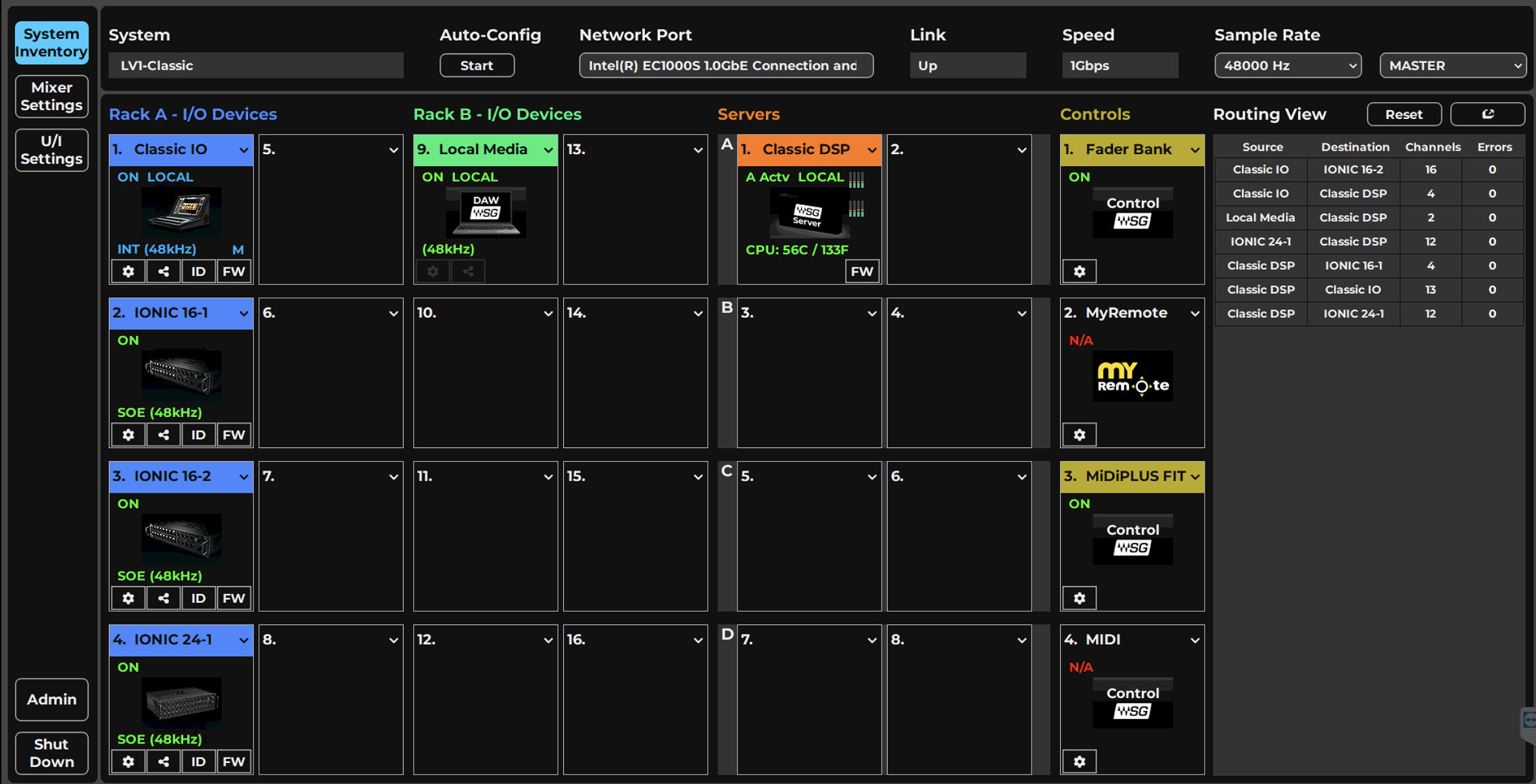
-
Auto-Config STARTStarts the Start Assignment routine for automatic configuration. When LV1 Classic starts, the 16-channel onboard I/O is assigned automatically; this routine adds additional external I/O devices such as stageboxes.
-
Sample Rate Selector MenuSets the system sample rate when the mixer is the sample rate master, and the window displays the system's sample rate. The menu is disabled when the mixer is a sample rate slave, since it can set the rate only in master mode.
-
System (View Only)Identifies and displays the LV1 Classic system you are using, relevant when working on a multi-LV1 super system where several LV1 Classics share a network. The system name can be changed in the Admin Kiosk.
-
Sample Rate Master/Slave SelectorControls whether the mixer is the sample rate master or a slave, determining how the sample rate of the system is established.
-
Network Port (View Only)Identifies the SoundGrid network port used by the internal network.
-
Rack A — I/O DevicesI/O Rack A assigns up to eight I/O devices, which can be hardware devices, software I/Os (drivers), or a combination of both.
-
Link (View Only)Reports the status of the internal Ethernet connection to the computer running the eMotion LV1 software. Options: UP / DOWN / INVALID.
-
Rack B — I/O DevicesI/O Rack B is identical to Rack A and is used for additional I/O device assignments.
-
Speed (View Only)Reports the SoundGrid network speed. Options: 100 Mb/sec, 1 Gb/sec, or N/A.
-
Servers RackAssigns SoundGrid server(s) to the rack. The first server assigned is the primary server; additional servers are redundant (marked "RSGS") and a redundant server automatically takes over if the primary malfunctions.
-
Controls (Control Protocols Rack)The Controls rack assigns control surface devices.
-
Routing View PanelDisplays the status of network connections, with each row representing a one-way patch between two devices or between a device and the main server. The panel can be floated and moved to any location.
-
Populated Device SlotWhen a device has been assigned to a slot, its icon appears here. The icon contains information about the device.
-
Empty Device SlotA slot with no assignment is labeled "Add Device."
-
ADMINClick Admin to quit LV1 and open the Admin kiosk. This is used for system configuration, updates, and troubleshooting.
-
SHUT DOWNStarts the Device Shutdown procedure. Before shutting down, the mixer prompts you to save the current session.
The System Inventory page is used to assign and manage I/Os, servers, drivers, and controllers. The top portion of the page deals with network status, while devices are assigned in the racks below.
System Inventory Page Displays and Controls
This section describes the controls and menu items on the System Inventory page, followed by examples of how to use the System Inventory page in order to set up the mixer (Setup > Configuring a Basic Mixer Setup).
Automatic Configuration
When you start LV1 Classic, the 16-channel onboard I/O is automatically assigned. Additional external I/O devices, such as stageboxes, can be added manually or by using the Start Assignment routine:
- Connect external I/O devices to the Ethernet switch on the rear panel.
- Click Start, then Add. This maintains current connections, scans the SoundGrid network, and adds new devices:
- New I/Os appear after existing ones in the patch.
- New I/Os are initially slaves to the original I/O.
(Setup > Using the System Inventory Page > Configuring a Basic Mixer Setup).
System
Identifies and displays the LV1 Classic system you are using. This is relevant if you are working on a multi-LV1 super system, where several LV1 Classics share a network. You can change the system name in the Admin Kiosk.
Link (View Only)
Reports the status of the internal Ethernet connection to the computer running the eMotion LV1 software.
Options: UP / DOWN / INVALID Speed (view only) Reports SoundGrid network speed. Options: 100 Mb/sec, 1 Gb/sec, N/A.
Sample Rate Controls
Sample Rate Master/Slave Status Selector
Controls whether the mixer is the sample rate master or a slave. As such, it determines how the sample rate of a system is established.
Sample Rate Select Menu
Sets the system sample rate when the mixer is the sample rate master. The Sample Rate window displays the sample rate of the system. The menu is disabled when the mixer is a sample rate slave, since it can set the sample rate only when in the master mode.
Supported sample rates: 44.1Khz, 48Khz, 88.2Khz, 96Khz
The sample rate of the clock master device can always be set from its control panel, whether the mixer is in Sample Rate Master or Slave mode. Sample rate is discussed later in this chapter (Setup > System Inventory > Sample Rate Master vs. Sample Rate Slave).
- Click Admin to quit LV1 and open the Admin kiosk. This is used for system configuration, updates, and troubleshooting.
Device Racks: Configuring and Managing Network Devices
Device Racks are used to assign and control the hardware and software I/Os, servers, and controllers available on the network. Use these racks to set up a new configuration or to modify an auto-configured setup.
Device Racks A and B
Racks A and B assign hardware and software I/O devices to the mixer. Racks A and B can be used interchangeably and are separated only for convenience. For example, some engineers dedicate one rack to FOH and the other to monitoring.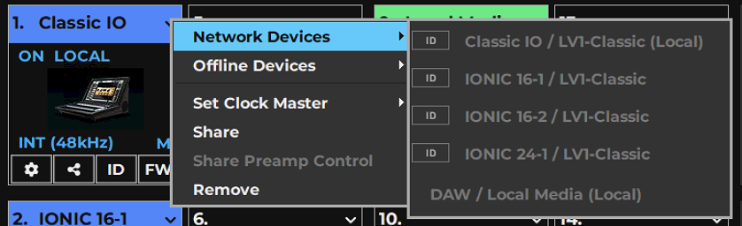
A rack consists of eight slots, each of which can hold one I/O device. The arrow in the rack slot opens a drop-down list of devices that are part of the mixer’s SoundGrid network.
Available devices are shown in regular type. Devices that are not available for assignment are grayed out.
Network Devicee List displays the devices in the connected SoundGrid network, select a devcie to assign to the Devcie slot.
Offline Devices are used for preproduction or for any need to prepare routing and patching for a device that is not yet conected. In the list you will find all SoundGrid compatible devices.
The rack slot number determines the device’s order in the Patch window and in certain drop-down menus. While device sequence is not important, but some engineers choose to dedicate one rack for PA devices and the other for monitoring.
The ID button next to the device name activates a changing-color LED on the device front panel to help identify the physical unit.
I/O Device Racks Displays and Controls
There are several status indicators and buttons on the icon itself and just below it. The color of the text in the slot indicates the master/ slave status of the device.
(Blue=Master, Green=Slave, Red=Device not available, Orange=Shared Device)
Indicator | Possibilities | A | |
|---|---|---|---|
Slot Sequence # | Rack A 1–8; Rack B 9–16 | Indicates the rack slot number. I/Os appear in the Patch window in this sequence. | |
Device Name | Text entry | The device product name followed by a number is the default name. Change the device name by double-clicking on its Name Box. | |
Devices Menu | Drop-down menu | Used to add and remove devices from the slot and to set the device as clock master. | |
Device Status | On | Device is active. | |
NA | Device is unavailable. Likely causes:
| ||
Offline | A virtual device is assigned to this rack slot for offline preparation of sessions without I/Os connected. All device patching will be maintained when the session is launched on a complete system. | ||
Clock Source | INT, SOE, AES, WC | Clock source of this device. The SoundGrid network operates in a Sync on Ethernet network. Non-SEO devices can, in some instances, connect to an SOE device, and then join the SOE network. | |
Sample Rate | 44.1, 48, 88.2, 96 kHz | Sample rate of device. | |
Clock Master | M (Master) / blank = slave | Identifies the device as the clock master of the SOE network. | |
Control Panel Access | Gear button | Click to access the device’s floating control panel to adjust preamps, configure channels, and control clock. Refer to the I/O device manufacturer’s user guide for more information. Up to five floating windows can be open at once. |
Enable Sharing | On or Off | Permits this device to be shared with other LV1 systems. | ||
ID Hardware | Locate hardware device | Activates lights on the front panel of the hardware device associated with the icon. | ||
FW | Status of the device’s firmware: | |||
Gray | Firmware is compatible with installed mixer software. | |||
Blue | Firmware is compatible with installed mixer software, but a newer version exists. It should be updated as soon as possible. | |||
Red | Firmware is not compatible or is out of date. Click the FW button to re-flash device. | |||
Offline device | Red | Device is offline. It can be assigned to the console and configured. Settings will be applied to the hardware device when it is available. | ||
Shared Device | Indicates that this device is shared from another LV1 system. | |||
Shared Driver | Indicates that this driver is shared from another LV1 system. | |||
I/O Devices Menu Items
Once an I/O device has been assigned to a rack slot, additional menu items are available.
LV1 Classic appears in three places in the System Inventory.
- The Classic I/O appears in the I/O Devices rack.
- The Classic server appears in the Servers rack.
- The Fader Bank appears In the Controls rack.
Menu Item | Possibilities | Function |
|---|---|---|
Set Master | A list of all devices that can be used as a clock source for the SoundGrid network. | Designates the device as the SOE network clock master and other devices as clock slaves. The letter “M” and the blue text in the slot indicate that the device is the master. |
Share | Check/Uncheck | Allows sharing of I/O channels on this device with other systems. |
Share Preamp Control | Check/Uncheck | Allows remote users to control the preamps of the shared device. |
Remove | Releases the device, making it available to other drivers. |
When you remove a device from a slot, you have two options concerning how to treat the existing patches for that slot.
Keep maintains the internal patching from any I/O that will be assigned to the slot.
Remove clears all patches for the slot.
This configuration is saved as part of the session.
I/O Devices Drivers Menu Items
Menu Item | Possibilities | Function |
|---|---|---|
Set Main Driver | Assigns main driver. | Assigns this as the main driver. The second driver serves as a backup. |
Driver Channels | Range: 32–128 channels Default: 32 channels | Sets the number of channels assigned to the SoundGrid ASIO/Core Audio driver. More driver channels can increase network load and may require additional buffering. |
Driver Network Buffer | (Values in samples/milliseconds) 44.1 kHz and 48 kHz: 104/2.2; 288/6.0; 512/10.7; 1042/21.3 88.2 kHz and 96 kHz: 208/2.2; 288/3.0; 512/5.3; 1024/10.7 Note: If a driver is shared, network buffers for all drivers will be set to a minimum of 288 samples. | The network buffer helps the OS send synchronized information between the ASIO/Core Audio drivers and the I/Os through the network port. When many channels are going in/out of the driver(s) to several destinations, the Driver Network Buffer may need to be increased to reduce the possibility of audio drops or artifacts caused by overloading the network port driver. |
All computers on the network should have the same up-to-date versions of eMotion LV1 and SoundGrid driver installed. Download the latest version from Waves Central.
LV1 Classic I/O
The Classic onboard I/O provides 16 channels of mic/line input on XLR/TRS combo connectors and 12 line-level outputs on XLR connectors. There is also a stereo AES3 input and two stereo AES3 outputs on XLR connectors and two independent headphone ports. The specific I/O, including its preamps, is managed from the control panel.
Certain additional features, such as HMX and impedance selection, can only be accessed here.
Click the small Gear button at the bottom-left of the Classic I/O slot to open the control panel.
Control Panel Pages

The Clock, Input, and Output pages are used to configure and manage the unit. The About and System Info pages provide information about the unit, such as MAC address, SOE network master, firmware version, and more.
Input Page
The Input tab is used to configure the device’s 16 analog mic/line inputs.
- Preamp Controls Presets: Load and Save
- Input Meters Device Name in Inventory
- Preamp Input Gain Adjust Device Status (when red, device is offline)
- AES Input Meters Clip Level Indicator Selector
- Power Supply Unit Indicator: 1 or 2 Device ID
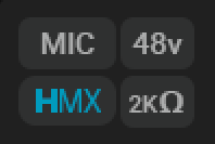
Preamp Controls
Mic/Line | Sets input level mode for mic or line inputs. Mic: Enables input level adjustment (-3 dB to +60 dB), for both XLR and TRS. Line: Gain is fixed. XLR is set to 0 dB, 7k ohms. TRS set to -6 dB pad, 14.6k ohms. |
48V | Phantom power: on or off |
Mic Impedance | Sets mic impedance: 2k ohms or 7k ohms. This enables proper pairing of the mic to the preamp. Some mics perform better at a lower impedance, while others excel at a higher setting. To a certain extent, 2k ohms was the standard impedance during the 1970s, 1980s, and 1990s. Since the 2000s, 7k ohms has become more prevalent as it is more linear and produces less signal loss, especially when performing analog splits before the preamp. However, the choice is not always straightforward as there is a subtle sound difference between the two impedances. Unless the impedance choice is obvious, experimenting with both options is recommended. |
HMX | Turns Waves Harmonic Enhancer on or off. Harmonic enhancement usually results in a more natural-sounding, warmer sound, as found in classic analog equipment. Bypass HMX for a more neutral sound. |
Input Level Adjust
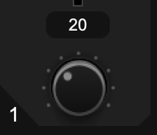
Controls the gain of the Classic preamps. Small values are used for line inputs and large values are used for mic inputs. Range: -3 dB to 60 dB (in steps of 1 dB)
A setting of 0 dB allows a +24 dB input without clipping. A setting of +20 dB allows a +4 dB input without clipping. The channel number appears on the left of the control, and the current gain is indicated in the box above.
Clip Level Adjust
Use the Clip Level drop-down menu to set the level at which clipping will be indicated by the LED in the meter. This does not affect the audio level, only the point at which clipping is indicated.
Range: -6 dB to 0 dB
Output Tab
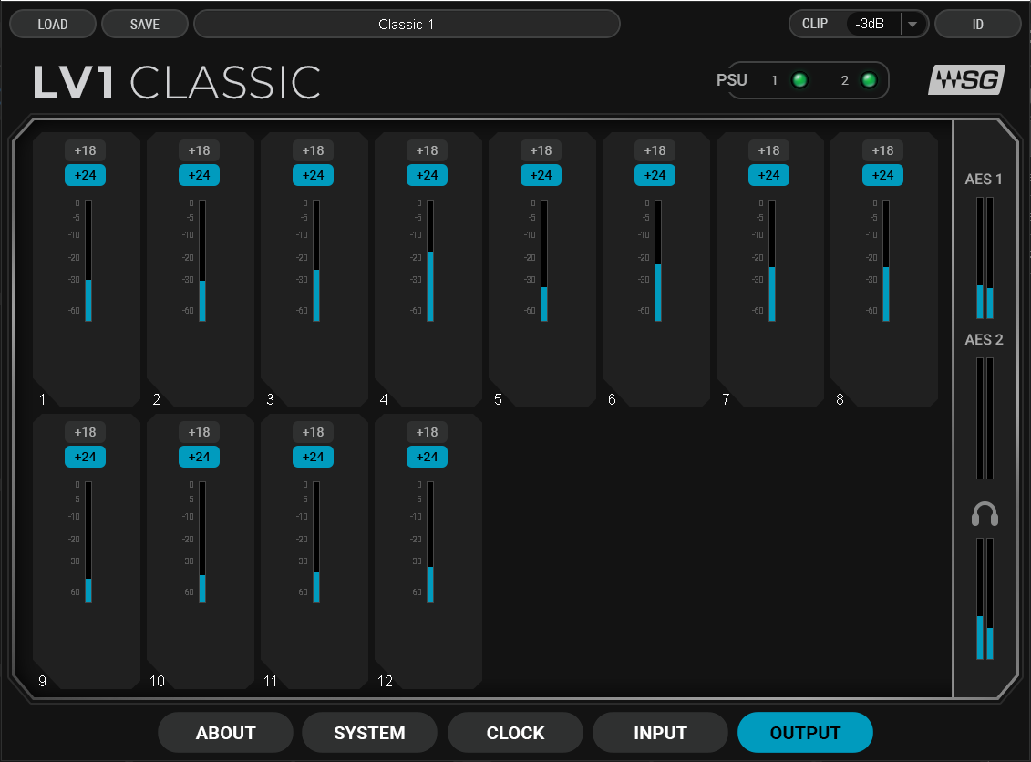
-
LOADLoads a saved I/O device preset. A preset includes all parameters in the Clock and Control panels, so you can reuse a configuration in future sessions or on another computer.
-
SAVESaves the current device settings as a preset. The preset includes all parameters in the Clock and Control panels for reuse in future sessions or to duplicate a configuration on another computer.
-
CLIPClip Level drop-down menu that sets the level at which clipping is indicated by the LED in the meter. It affects only the point at which clipping is shown, not the audio level. Range: -6 dB to 0 dB.
-
Line outputs 1-12The 12 line-level outputs of the Classic I/O, shown as metered output channels numbered 1 through 12.
-
AES outputsThe stereo AES output of the Classic I/O, shown here as AES 1 and AES 2 output meters.
-
Headphone outputStereo headphone output. The Classic I/O provides 2 stereo headphone outputs.
There are 12 line outputs, a stereo AES output, and 2 stereo headphone outputs.
Headroom Select | Select +18 dBu or +24 dBu mixer headroom. |
Analog Output Meters (dBFS) | -60 dB to 0 dB, +18 dBu and +24 dBu full scale line output levels. |
AES Output Meter | Level indication only; no input control. |
Headphone Meters | One meter for each headphone channel. |
Clock Tab
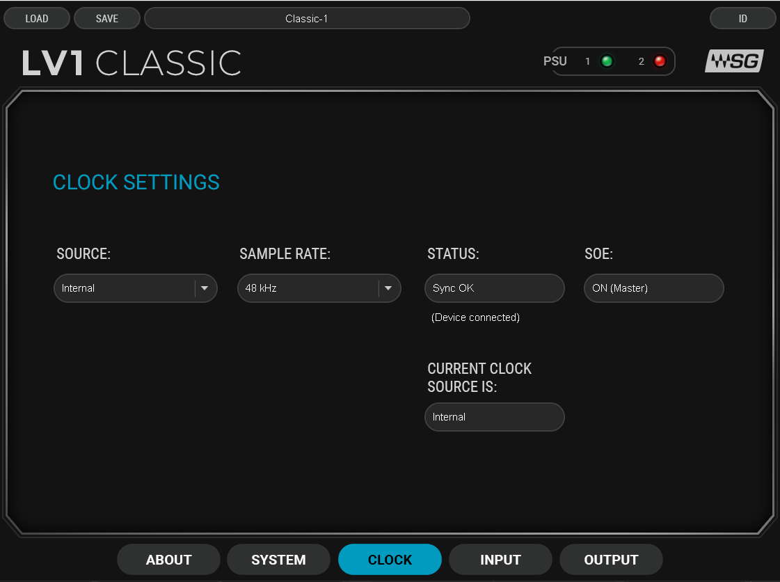
-
SOURCESelects the clock source used to manage the clock relationship between the Classic I/O and the SoundGrid network.
-
STATUSShows the current clock sync status. When the Classic is locked to the SoundGrid network via Sync Over Ethernet, the status indicates a successful sync.
-
SOESync Over Ethernet setting for the clock relationship with the SoundGrid network. The device can lock to the network over SOE or serve as the SoundGrid network clock master (Master).
-
Sample RateSelect the Device sample rate.
Use the Clock tab to manage the clock relationship between the Classic I/O and the SoundGrid network. The following image shows Classic locked to the SoundGrid network via Sync Over Ethernet (SOE). The device can also serve as the SoundGrid network clock master.
Source Select | Requests a clock source. If this source is unavailable, Classic will poll all other potential clock sources. If there are no available clock sources, Classic will default to internal clock. |
Sample Rate | When Classic is the SOE clock master and is set to internal clock, this drop-down menu is used to set the device’s sample rate (and hence the sample rate of the SOE network). When Classic is not the clock master, this window displays the SOE network sample rate. |
Status | Displays the device network sync status. |
SOE | Indicates SOE status (On/Off, SOE Master/SOE Slave) |
Current Clock Source | Indicates the actual current clock source. If the device is unable to sync to the requested clock, this displays the fallback. |
PSU | A dual power supply provides power redundancy. LEDs at the top indicate PSU status: when both LEDs are green, both PSUs are working properly. A red LED indicates a PSU that has been connected and is now malfunctioning or disconnected. A PSU that has not been connected will appear gray. When only PSU 2 (likely the redundant PSU) is operating, a white status light on the back of the console will blink. This means that PSU 1 is not working. |
System Info Tab and About Tab
The About page contains a description of the device. The System Info tab contains technical details about the device, including MAC address, firmware version, and module version. This information is useful for troubleshooting. Please have this information handy if you contact Waves technical support concerning the device.
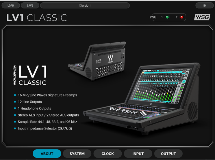
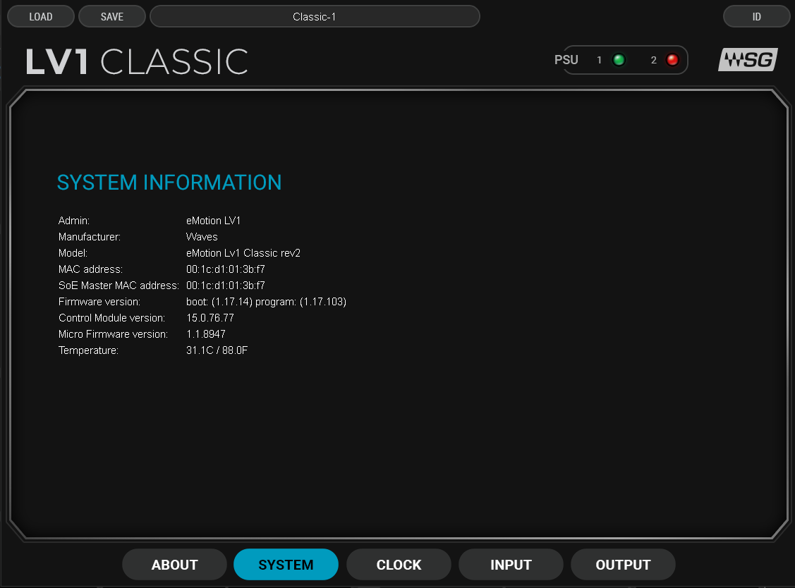
I/O Device Presets
You can save and load presets of device settings. A saved preset includes all parameters in the Clock and Control panels. Save Classic presets to use in future sessions or copy them to another computer to duplicate a configuration.
I/O Sharing
Device sharing enables networked LV1 Classic systems to share I/O channels with devices anywhere on a multi-user network.
Device sharing in a multi-LV1 system is best demonstrated with an LV1 Classic that becomes larger and, through device sharing, more flexible as needs increase.
Example One—FOH: LV1 Classic and One I/O On Stage (no sharing)
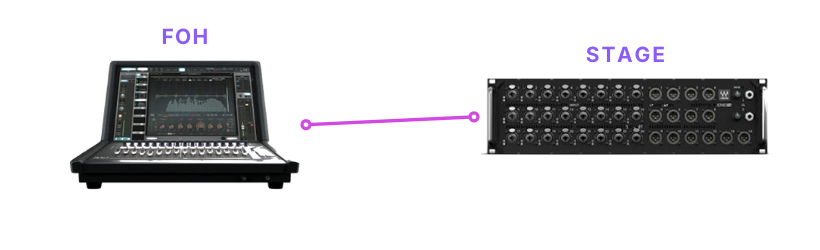
This single-LV1 system consists of a Classic console with its internal Classic I/O and an Ionic 24 I/O. The Ionic is onstage and is used for mics, DIs, and monitoring. The onboard Classic I/O covers PA and other FOH needs.
Because of Classic’s 4-port 1 GB Ethernet switch, you do not need an external one. Connect the console’s switch directly to the I/O devices.
Example Two—Device Sharing: Add a Monitor System
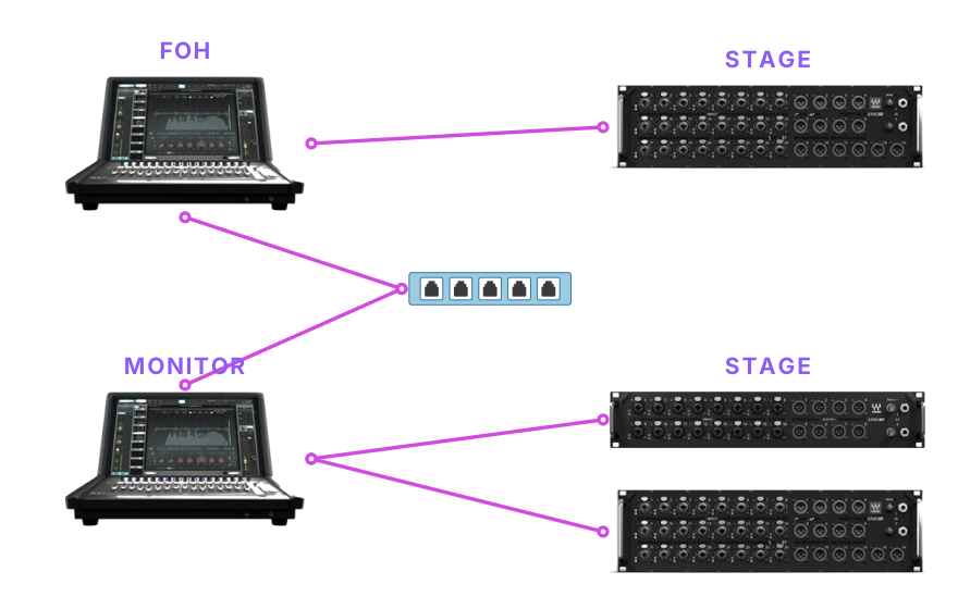
As your monitor needs become more demanding, you may want to add another Classic console that’s dedicated to the monitor mix. Device sharing is enabled. The FOH console can share its I/O devices with the monitor system, and the monitor console can share its Ionic 16 and Ionic 24 with FOH.
The 64 onstage I/O channels can be shared with either systems.
Connect the consoles via a 1 GB Ethernet switch. Do not use the onboard Ethernet switch to connect systems.
Example Three—Add a Third LV1 System For Broadcast or Streaming
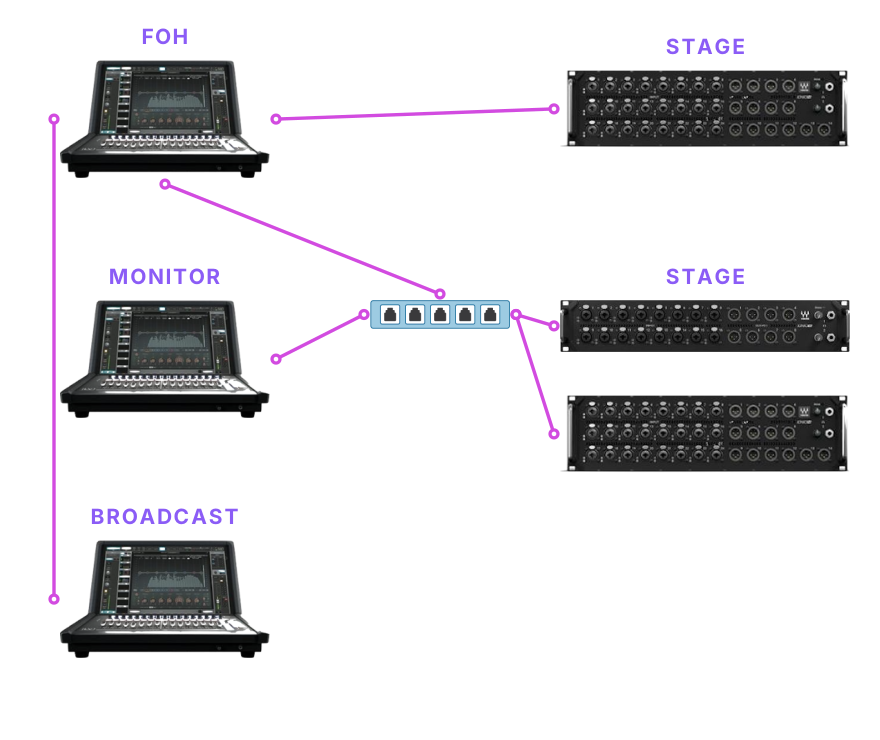
You can add a third console for purposes like broadcast or streaming. Since the streaming system has few I/O needs, you can likely assign I/O channels from other systems and use the 16-channel LV1 Classic I/O in this console.
This combined system now includes 136 I/O channels that can be assigned from any of the consoles.
Once a device is sharing enabled, any system can assign it to the inventory. The device appears in the device rack and behaves like an unassigned device—except that it can be anywhere on a multi-LV1 network.
The three-console network in example three has 136 assignable input channels that can be shared and used on any of the Classic consoles. Note that the actual number of shared I/Os may be less, due to network considerations.
Setup
An unshared device that is assigned to an LV1 Classic console’s inventory and that is not share-enabled is available solely to that console. Once the device is available to other users for sharing, the console is the manager of the device. Other systems (clients) can now assign free I/O channels from the managed device. A client can assign free I/O channels to its inventory, but with less control.
Enable Sharing on an Assigned Device To enable other systems to share from a drive that you have assigned to your system, follow these steps.
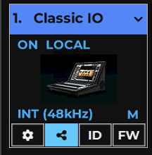
- Go to the System Inventory.
- Assign the device to your inventory (if not already assigned).
- On the assigned device you wish to share, click the Sharing icon. Other systems can now assign this I/O device to their inventories and patch available I/O channels.
- Sharing can also be enabled from the Device menu in the Mixer window and in the Patch window.
A shared device can have multiple clients (within the limits of the device’s maximum output to the network). A device, on the other hand, can have only one master. Each destination establishes a direct connection from the shared IO device, increasing the total outputs to the network.
When an I/O device is removed from the manager’s inventory, it becomes free and it can be assigned by any other LV1 system.
Assign a Shared Device to Your Inventory (client) To share I/O channels from a sharing-enabled system, do this:
- Select a device slot in the System Inventory.
- Go to the Device menu and choose a network device whose name is in italics (remote system) and not grayed out (this device is available to you). All assets in the combined systems are shown in the System Inventory of all users (see below).
This is how a System Inventory might look in a large shared system. The font color (white or gray) and its type (roman or italic) indicates the status of the devices in the network.
Classic I/O - 1 B-Ionic 24/Free A-Ionic 24/free C-Ionic 16 / SGQA0 Classic I/O - 2 DAW / MPB16 DAW / System 2 DAW /JP.local DAW / MAT-10PC ID Locally assigned device (your device, assigned to you, not free)
Unassigned devices Sharing-enabled device on another system (italicized) Device assigned to another system (grayed out, italicized) Unassigned driver Sharing-enabled driver on another system
Driver assigned to local LV1 Driver assigned to another system
Share Preamp Control
When the device manager selects Share Preamp Control in the Device menu, any client can adjust the preamp gain for any I/O channel on the shared device. All users sharing this device have equal control of preamp gain in any patched I/O channel.
Controlling gain in multi-system environments and retaining gain structure while other users are controlling preamp gain is described on the next several pages.
Patching Shared Devices
Patching Shared Input Devices
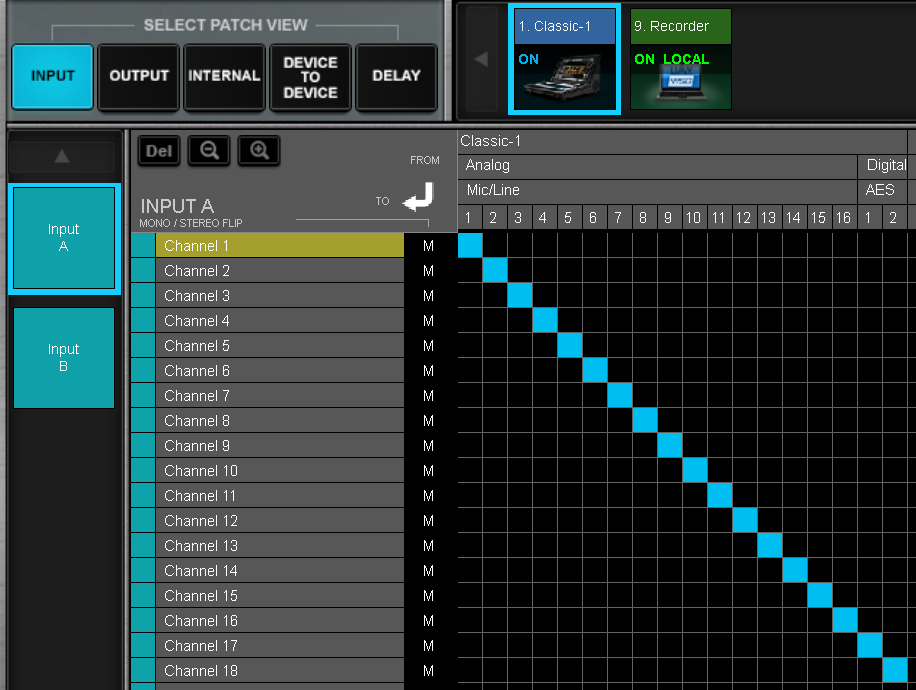
When a device is shared, its inputs are available to all users. Shared devices appear in the patch alongside non-shared devices.
Shared devices can also be patched in the Channel I/O menus of the Mixer window and Channel windows. In those windows, <share> indicates that the I/O channel is from a shared device.
Patching Shared Output Devices
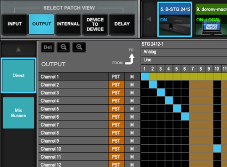
When patching a mixer output, remember that a mixer output channel can route to only one I/O channel (unlike an input, which can be sent to multiple mixer channels)
Once assigned, a shared I/O device appears in the client’s Output Patch window. The label “I/O Sharing, Remote Device” is shown on its icon. Patching shared I/Os follows the same conventions as patching unshared SOE devices. There are, however, a few considerations when sharing devices.
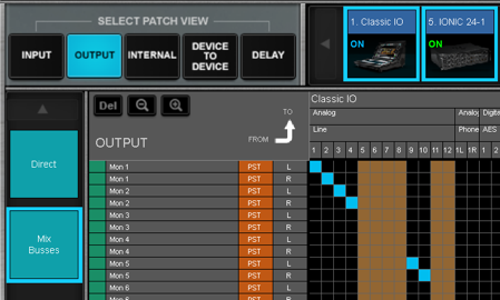
When an output patch is made in one system, the corresponding I/O channel in the other system is colored orange to indicate that the I/O channel is in use. Channels in the black field are available.
The same patching considerations apply to the Channel I/O menus in the Mixer and Channel windows.
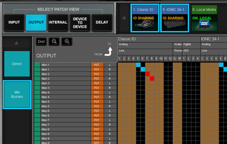
If the manager of a device patches to an I/O channel that’s already in use by a client, the preexisting client patch will turn red. The client is no longer patched to that I/O output channel.
A manager can always disconnect any I/O channel by repatching.
A notification alerts the client when the original patch is taken by the manager. Once the manager releases the patch, the connection will return to the client.
Removing Shared Devices
The manager of a shared device can remove the device from its inventory without interrupting sharing on the client devices by selecting Unassign the Device. The device will appear unchanged to the clients, and any client can become its master (if necessary). For the moment, the device is functioning, although it temporarily becomes orphaned (without a master). If the original system reassigns the device and reenables sharing, it will reestablish its master status.
If you choose to keep the device in your inventory but disable sharing, you will cut off existing clients from this device. Therefore, the manager cannot end sharing until all client devices are unpatched from the device.
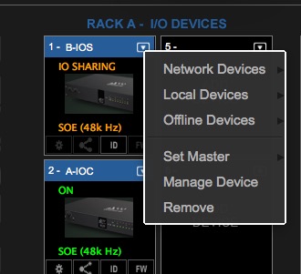
Similarly, a client can remove a device by removing it from its inventory. Select Remove from the Devices drop-down menu. In most cases, this will not result in an audio dropout.
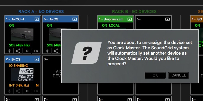
Even if the clock master has been removed from its owner’s inventory, the device will continue to operate and distribute clock. Only if the owner of the device choses to assign a new clock master, or another user claims Master status of the device and changes the settings, will other devices be affected.
If the Sharing LV1 Becomes Unavailable
If the manager of a shared device is no longer available to the network, clients of the device can still use it, and the shared device will continue to function. Below is a common example.
There are two systems and an additional Ionic Stagebox.
- Classic A is managing the Ionic, which is shared.
- Classic B shares from the Ionic Stagebox as a client.
If, for any reason, System A is removed, System B can continue using the Stagebox. As long as the Ionic device remains powered on and connected to the SoundGrid network, it will pass audio, and current settings will be maintained.
The device is still owned by the missing System A, which means System B cannot access the device’s control panel or establish preamp sharing. If System B had been granted preamp control privileges beforehand, it will still be able to control shared preamps. If System B was not assigned preamp privileges, it will need to take over as the master of the Ionic.
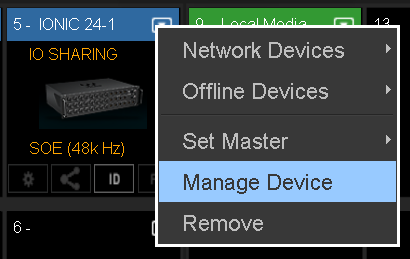
Select Manage Device from the client’s Device menu and the device will appear in the client’s inventory as a local SOE device. The device can then be assigned to the new system.
There may be situations where a device is not managed by any LV1 system. If a system outside of the current group assigns the drive and claims manager status, the unowned device will reset to its default state and sharing will be disabled. Old connections are lost, but new connections can still be established.
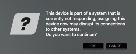
Should you get this prompt, check other connections to the system.
Device Management Overview
- When a free device is assigned to a system’s inventory, the system becomes the manager of that device. The device manager can configure any of the device’s parameters, such as clock settings, special device parameters, gain, phantom power, and more. Only the device manager can update firmware.
- An unshared device can only be used by its owner. Other users on the network will not be able to assign it.
- When sharing is enabled for a device, other systems can share its I/O channels. Clients have limited control over many device parameters.
- The manager can permit remote preamp control of any or all devices with which it is sharing.
- For a client to set these manager-privileged parameters, it must claim manager status of the device by going to the Manage Devices menu item. This does not affect any existing connections—it merely changes the permissions.
Clock in Shared Systems
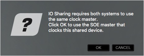
When a device is shared by two or more systems, all systems must be locked to the same clock master. If a system enables sharing on a device that is part of another system, it must align with that system’s clock. In such cases, the prompt shown (left) will appear. Click OK to set the clock of the shared device as your system’s clock. This clock master then becomes the SOE clock master for all the devices in the shared SoundGrid network.
If the device that is being removed is serving as the SEO clock master, another device can assume that role.
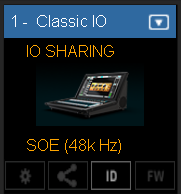
A small “M” on the device icon of a shared device indicates that the device is the clock master for the entire super-network.
For example, let’s say you begin with an unshared system of four devices. One of those devices is the master of the SOE network and this status is logged by LV1. When sharing is enabled, the system may designate a new clock master. As the network evolves, the clock master may change multiple times. Should you decide to disconnect from the shared system, simply deselect Sharing and your system’s clock will be restored to its unshared configuration. eMotion LV1 Classic keeps a log of each device’s clock master status, whether the device is an individual system or part of a multi-system network.
Reassigning Clock Master
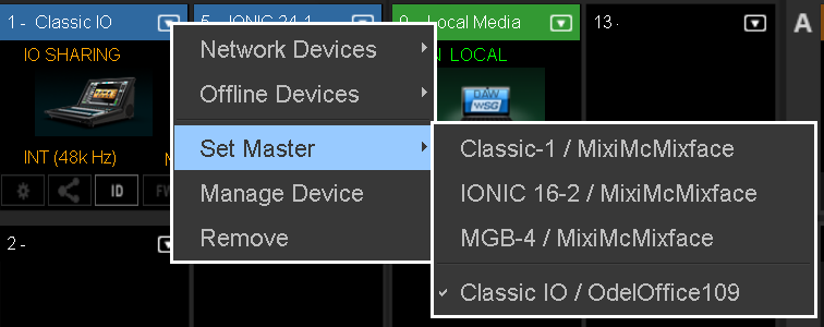
To become the new master of a device and adjust its parameters, go to Set Master in the Devices menu and select the device.
To become the new master of a device and adjust its parameters, go to Set Master in the Devices menu and select the device. If the clock source is removed from a multi-system network, the network you can assign another device as the clock master.
It’s important not to confuse the clock master with the manager. Manager refers to the system that has admin privileges in a shared device. Clock master is the device providing clock for all devices in the network. Only the clock master can change the sample rate for the entire system.
Sample Rate Master vs. Sample Rate Slave
The clock master device sets the sample rate for all devices in the system—everything locked to its clock adjusts to its sample rate. Although the clock master distributes clock at a specified sample rate throughout the system, it does not necessarily determine what that sample rate will be. This is fixed by the sample rate master, which could be the clock master, the mixer, or another system that provides clock. Almost any device with configurable sample rate settings can act as a sample rate master.
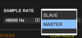
- Slave: The system will accept the new clock master and lock to the new sample rate. Devices that are unable to make this change will be removed from the sharing group.
- Master: The system will refuse the request, and all devices locked to the previous master will be removed from the sharing group. This menu controls whether the mixer is the sample rate master or a slave. Consequently, it determines how the sample rate of a system is established
When set to Master mode, the Sample Rate menu setting instructs the clock master device to change its sample rate. This in turn changes the sample rate of all SoundGrid devices in the mixer system. The clock master supplies the requested sample rate from any of its available sources (e.g., AES, S/PDIF, Word Clock, Internal). The priority of clock sources differs according to the specific device. If none of these sources can switch to the desired sample rate, the clock master’s icon will turn red, as will the sample rate indicator. Audio will mute. At this point, you can choose to stay at the previous sample rate or find another means of clocking the system. Or remove yourself from the network.
When set to Slave mode, the mixer system sample rate is determined by another system. When the sample rate of the clock master device changes, the mixer automatically adjusts its sample rate to match.
The mixer system can receive clock from another system.
Servers
LV1 Classic comes with a built-in server responsible for running the console and performing plugin processing. This server is automatically assigned to the console upon launching and must always be assigned to slot 1.
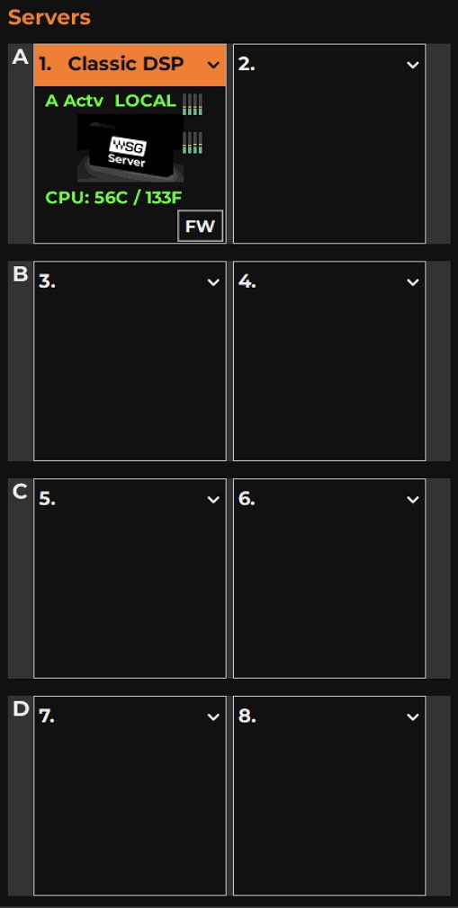
You can assign up to three more servers for additional processing and up to four servers as backups. And you can also replace main server. ¹
¹ You can replace the onboard server with a different one if needed. Unassign the Classic server and reassign the replacement in its place.
The Servers Rack is used to assign, remove, and configure SoundGrid servers. Servers are assigned and removed in the same way as I/O devices.
Servers are organized into groups of two: A, B, C, and D. These groups are assigned to specific channels for processing, with assignments configured in the Channel and Mixer windows.
The server in Slot A is used for running the mixer and handling plugin processing. Regardless of how many additional processors are added, there must be a server in this slot.
The first server assigned to a group becomes the active server for the group and is labeled “Active.” The second server assigned to the group acts as the redundant server and is labeled “Backup.”
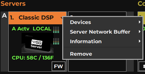
Servers are assigned and configured via the drop-down menu.
Menu Item | Possibilities | Function |
|---|---|---|
Devices | Drop-down menu | Choose from the available servers on the SoundGrid network. A server that is already assigned to an LV1 and is not shared is unavailable and grayed out. |
Server Network Buffer | (samples/milliseconds) 40/0.8 56/1.2 80/1.7 112/2.3 160/3.3 224/4.7 | Sets the size of the internal server buffer, which influences the time it takes for audio to stream from the I/O to the server and back. This setting impacts the speed of real-time processing. Each mixer connection pair represents a server processing buffer, so the buffer size influences latency in routing where there are multiple connections. If you encounter pops or other errors, increase the buffer setting. |
Information | (N/A) | Reports technical details about the server, including server link speed. When Server link speed is 100 Mbps or lower, the server name will appear in red text. This typically indicates a physical connection is broken. |
Test Redundancy | Runs your session through the main and redundant servers separately to confirm that each can handle the session without failure. If the redundant server cannot meet the session’s processing needs, the session may not perform effectively if the main server fails. | |
Remove | Releases the server from the local LV1, making it available to others. |
Server Groups B, C, and D are insert points to server A. Audio being processed in servers B, C, or D will be streamed round trip to/from the main server.
This additional round trip introduces a minimum latency of 64 samples. The actual latency will depend on the Server Buffer Setting.
The processing power of a server group is defined by the power of its active server. Since server A is the principal server, we recommend that you assign your strongest server to this slot.
Additional servers should be placed as close as possible to the main server. Ideally, they should also be connected to the same network switch as the main server assigned to Group A.
Server Assignment Notes
Server Indicators on the Icon
Server Status is indicated by the color of the text displayed on the server icon.
Green | The server is present and operational. |
Gray | The server is assigned but is not available. “N/A” is displayed. |
Red (Name only) Red (Temperature) Red (On and FW) Red (On only) | The server is unsupported. CPU is overheating. The device firmware is incompatible. Reduced link. |
DSP Meters
The meter bars on a server icon indicate DSP usage of each of the server’s cores. There is one meter per core.
The solid bar areas display average DSP use per core. The yellow lines indicate peak usage, which is also displayed as a percentage above the line. Certain plugins can exhibit a high average/peak DSP ratio. This may cause overloads (momentary or constant) that result in audio drops. When adding many of these CPU-intensive plugins, the peak and average indicators will drift apart. In such cases, you may need to disable or remove certain plugins.
Average | Peak | Status |
|---|---|---|
Green | DSP peak value: 1% to 84% | System is stable. You can add more plugins. |
Yellow | DSP peak value: 1% to 84% | Monitor the meter status and be prepared to remove some plugins and/or increase the network buffer size. |
Yellow | DSP peak value: 85% to 99% | Monitor the DSP meter status. Remove some plugins and/or increase the network buffer size. |
Red | DSP load is beyond the limit. Remove heavy-load plugins immediately. |
CPU Temperature Indicates the temperature at the server’s core, displayed in Celsius and Fahrenheit. Refer to the device’s user guide for temperature limits.
Operating ranges: ambient temperature is 0–35°C; Server CPU working temperature is less than 80°C.
Using a Backup Server
Assign a second server to provide redundancy in case the primary server fails. The switchover to the second server occurs automatically and the switchover time depends on the session size. During this period, sound is muted. Redundant servers are labeled “Backup” in the Inventory.
The second server in a server group is used only for redundancy. A server group can have only one active server.
Test Redundancy
This test runs your session through the main and backup servers separately to confirm that each can handle the session without failure. If the backup server cannot meet the session’s processing needs, the session may not perform effectively if the main server fails.
The result of this test is either pass or fail. If the redundant server passes, then all is well. If it fails, you must upgrade to a faster redundant server or reduce the number of plugins in the session.
Redundancy with Multiple-Server Systems
- If the active server in Server Group B, C, or D fails, its redundant server will take over, as described above.
- If there is no redundant server in the group, the plugins in racks assigned to that server group will be bypassed, but the audio will keep flowing. When the server reconnects, there will be a short sync and the channels that are patched to that server group will start processing the plugins again.
- Should the redundant server fail, audio will not be completely lost. Rather, rack processing will be bypassed and the audio will remain unprocessed until the disconnected server is back online. In such cases, any added plugin latency will remain calculated, unless rack processing is assigned to Server Group A.
Multi-Server Operation
A server group can be assigned to any mixer channel—all plugin processing on that channel will take place on the designated server. This allows you to distribute your DSP load between servers to get optimal performance from them. DSP-heavy plugin racks can be assigned to different server groups to balance the load. You can assign these DSP-heavy channels to stronger servers, while assigning lighter racks to older or less powerful servers.
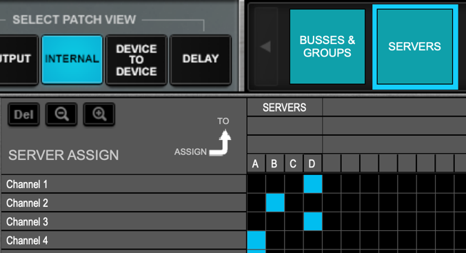
Server groups are assigned in the Patch Window internal Patch View (shown here at the left), which provides an overview of all or the server group assignments.
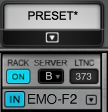
You can also assign a server group to the selected channel using the server-assign drop-down menu at the top of the plugin chainer in the Channel Window.
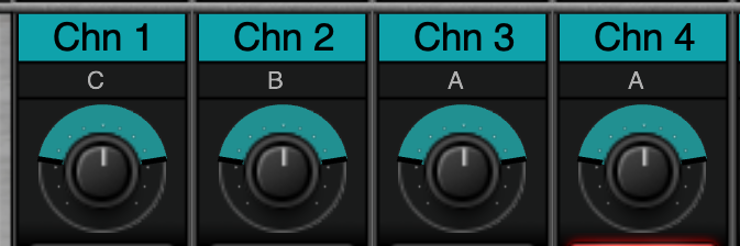
In the Mixer windows, the assigned server group is displayed beneath the channel’s name. You cannot set the server group assignment from the Mixer windows.
External Control Devices
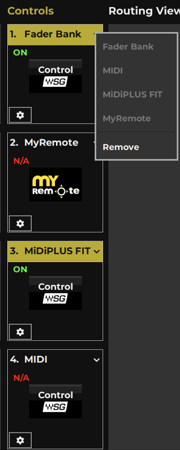
- Use the Controls Rack to assign external controllers to the mixer. Choose between protocols for Classic Fader Bank, MIDI Controller, and MIDIPLUS FIT, as well as mobile app remote controllers. Assigning controllers is very similar to assigning I/O devices and servers.
- There are two common reasons for adding controllers:
- Add Control surfaces to increase the number of channels that can be controlled simultaneously. This essentially gives you a wider console, or lets you control both Mixers at the same time.
- Enable artist-adjusted monitoring and remote-controlled LV1 adjustment away from the FOH. These applications for mobile devices are all managed via the MyRemote controller.
Possibilities | Function | |
|---|---|---|
Assigned Control Name | Displays selected control protocol. | |
Controller Device Status | Displays presence and status of the device | N/A >Device corresponding to the selected protocol is not present or is not functioning properly. On > Device is present and operational. |
Access Control Panel (Gear Button) | Momentary switch | Opens the control panel of the selected controller. |
Controls Drop-Down Menu | List of available control protocols. | All available controller categories are listed, whether the associated device is connected or not. |
Remove Control | Unassigns the current control protocol. |
Controller Menu Items
To access a controller’s control panel, assign the controller and click the gear button.
Fader Bank is a control panel for the onboard tactile controller. It provides a classic workflow with faders, knobs and toggles. Learn more about the fader bank in Appendix A in this user guide. This is the default controller.
MIDI Controller is an interface for remote control of functions using MIDI protocol. Refer to Appendix B for more information.
MIDIPLUS FIT is an external controller for LV1 that can be added to extend the tactile control options. Refer to the MIDIPLUS FIT user guide for details.
MyRemote is a control panel that enables global control over the mobile applications used to remote control all or parts of LV1 Classic and produce onstage-controlled monitor mixes.
Refer to the Waves Mobile Apps Startup Guide to learn about MyRemote and the following mobile apps that it runs.
MyFOH | Enables the FOH engineer to remotely adjust critical LV1 controls from anywhere in the venue when listening from a static FOH position is inadequate. |
MyMon | A personal monitor mixing app for musicians. |
MRecall | Allows remote loading of LV1 scenes from the stage or elsewhere in the venue. |
MixTwin | Mirrors LV1 to enable remote control away from FOH. Refer to the MixTwin product page for details. |
Routing View Panel
The Routing View panel displays the status of network connections, showing how audio streams from one device to another. Each row represents a one-way patch between two devices or between a device and the main server. Note that a round trip between a server and a device is reflected in two one-way streams.
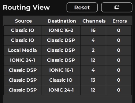
Routing View Columns
Source device
The origin of the network connection (I/O, server, driver).
Destination device
The destination of the network connection (I/O, server, driver).
Channels
The number of SoundGrid channels in the connection. A SoundGrid network channel reflects a one-way trip between a device and the server or between two devices. This includes patches made in the Device-to-Device page in the Patch window, something that is not visible in the Rack or Overview windows.
Errors
Displays the count of the network packet errors for the connection. When an error occurs, the display flashes, and the count is increased by one. Click Reset to clear the error counts.
Troubleshooting Network Error
- A high CPU average load value means that the network line carrying the connection may be reaching its limit, potentially causing dropouts. Reduce the number of channels on this connection to lower the network load.
- A low CPU load, combined with audio drops, on a connection from a server might indicate that the server is causing the drops. If the server’s peak CPU is high, reduce the server load.
- A low load and low SoundGrid server CPU might indicate a faulty cable.
- Widespread audio drops can indicate that the switch or a cable may be faulty.
Other controls Reset Clears the Error count.
Float
Un-docks the Routing View window
Mixer Settings
Use the Mixer Settings page to establish system-wide parameters and define how new sessions are configured.
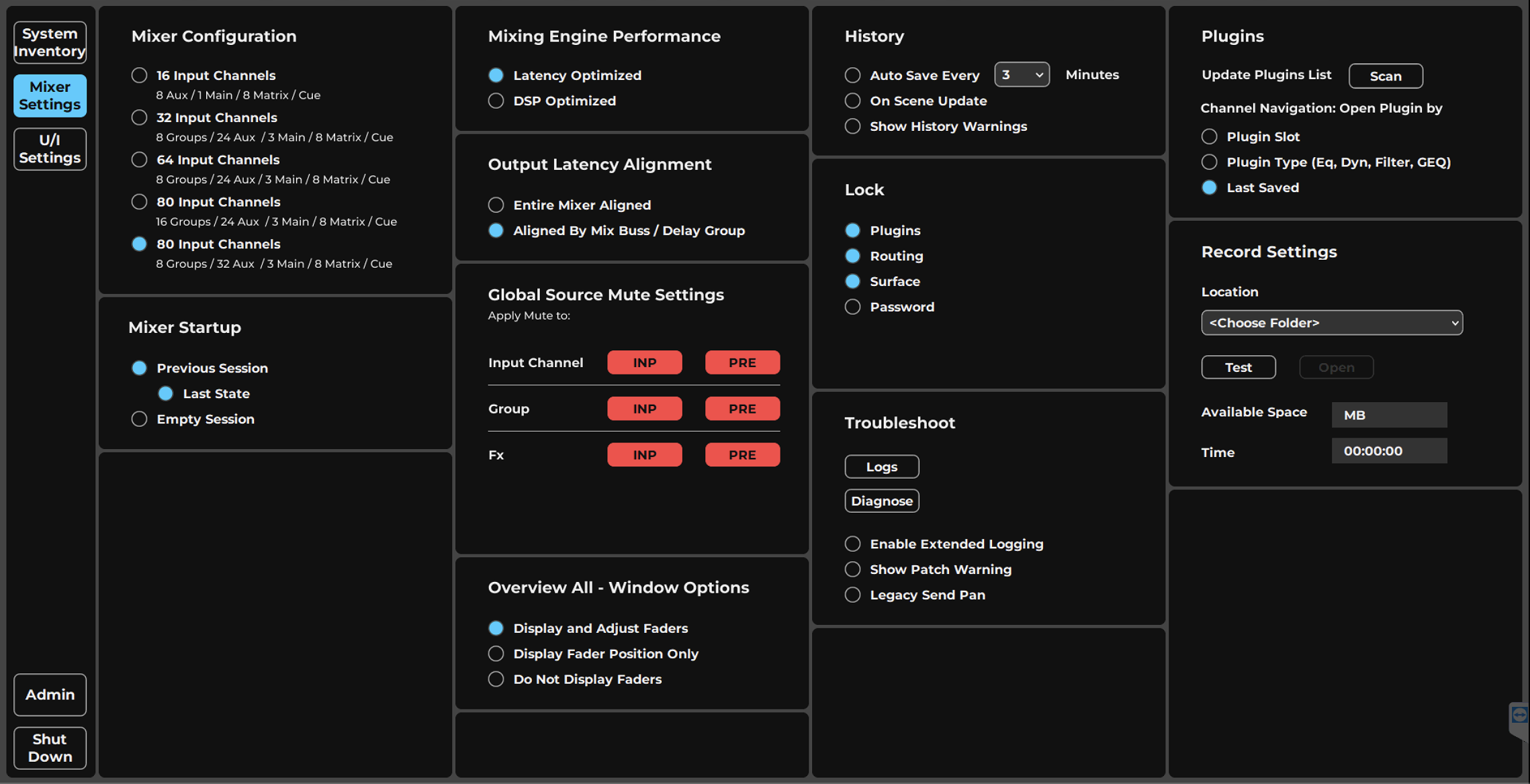
-
Mixer ConfigurationSets the size and configuration of the mixer; the mixer can be 16, 32, 64, or 80 channels (plus groups, aux, main buss and matrix) depending on the selected configuration. The maximum size depends on your license.
-
Mixing Engine PerformanceSets the mixer internal processing priority, trading zero internal routing latency in Latency Optimized mode against improved DSP efficiency with added latency in DSP Optimized mode.
-
Output Latency AlignmentSets the alignment behavior of output I/Os. Plugin/buss delay compensation is calculated automatically per group.
-
Mixer StartupDetermines the startup condition of the mixer, such as restoring the previous session, its last state, or starting an empty session.
-
HistorySets the rules for automatic saving. The mixer stores an unlimited number of auto-saved files using the .emo extension in a separate folder; Show History Warnings alerts you as the History folder fills, and deselecting it triggers a "Do not
-
LockLocks the entire mixer surface or selected mixer actions to prevent unintended structural changes such as adding, removing, or copying plugins or changing external patches. You can also lock the application interface, with or without a pass
-
TroubleshootingEnable Logging provides verbose logging for troubleshooting; click Logs to view or copy log files, and Diagnostics to scan your computer and generate a report. Show Patch Warnings issues a warning whenever routing changes are made in the Pa
-
PluginsUpdate Plugins List scans the system for new plugins, and the Plugin Menu Filter sets whether all Waves plugins or only licensed ones appear. Channel Navigation determines which assigned plugin opens when moving between channels (by Plugin
-
Local Media RecordingUses the Record Settings panel to select and test the recording location for the local media device, then route recording and playback through the console.
-
Global Source MuteSets which sources are Muted when pressing Mute on a channel. For example when sending pre fader out to recording it should not be affected by mute.
-
All Overview WindowSet the Overvew All display and control mode. Full fader and mute control, display fader position only (no control) and display only meters for clear meter bridge workflow.
Mixer Configuration
The Mixer Configuration Panel sets the size and configuration of the mixer. The mixer can have 16, 32, or 64, or 80 or channels, and up to 16 stereo groups, 32 stereo aux channels, an L/R/C/M main buss, and an 8-channel stereo matrix channel, depending on the selected configuration. The maximum mixer size depends on your license.
If you are using an LV1 Classic, add an 80-channel license to enable two additional configurations. They are basically the same, except for these differences.
Option1: 80 input channels, 16 groups, 24 monitor aux mix busses Option2: 80 input channels, 8 groups, 32 monitor aux mix busses.
Each configuration provides an L/R/C/M main buss, and an 8-channel stereo matrix channels Changes made in the 80-channel configurations may be reflected in the Channel mode, Channel, window, navigation menus, side chain, user keys, and scope and recall safe panels.
Mixer size is normally established when a session is created, but you can change the mixer configuration of an existing session. Please note that if you reduce the number of channels in a session, the parameters in channels that are no longer part of the session will be discarded. Save a session under a revised name before you reduce its size. Mixer Layers without any channels are unavailable and their buttons are grayed out.
Refer to Appendix A of this manual for details concerning mixer licenses and configurations.
Mixing Engine Performence
The Mixing Engine Performance panel sets the mixer’s internal processing priority, which affects DSP performance.
In the Latency Optimized mode, a processing cycle must include all signal processing paths, so there is no internal routing latency. However, processing in this mode can be less DSP efficient with certain plugin processors. In the DSP Optimized mode, processing can spread across several buffer cycles, regardless of signal path position. This parallel processing provides greater DSP efficiency, with increased latency on certain signal paths.
The network buffer is the amount of time it takes for audio to stream from the I/O to the server and back. This determines the maximum latency for a processing route. Set the Server Network Buffer size in the Server rack of the System Inventory page.
Internal Routing | Server Network Buffer |
|---|---|
40–56 samples | 0–32 samples |
80–112 samples | 0–64 samples |
160–224 samples | up to 128 samples |
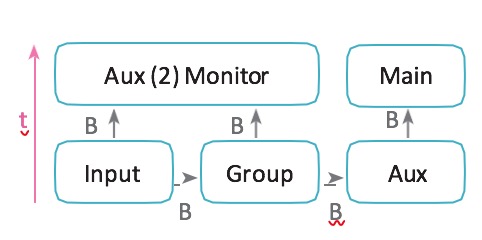
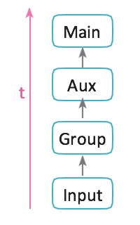
t = Determined by Server Network Buffer Example (Latency Optimized Mode) I/O Input Group Aux Monitor I/O Latency = 0 samples
In the Latency Optimized mode, processing takes place in a linear manner. All processing must be completed within one buffer cycle. There is no added latency in mixing, but plugins that exhibit large processing spikes can delay the entire processing chain beyond the limits of the network buffer. This is indicated on the DSP meter as a large average/peak DSP ratio (“B” in the image below).
The green area displays average DSP use. The orange line shows peak use. If this ratio is especially large, the processor may overload. A solid yellow meter (“C”) indicates that peak DSP load has reached 85%. To avoid audio drops, adjust your DSP use: (1) rebalance server assignments if you have more than one active server, and (2) remove or disable whatever plugins you can. If this doesn’t help, switch to the DSP Optimized mode.
t = Server Network Buffer + sum of all B paths Example (DSP Optimized Mode) I/O Input Group Master Aux Monitor I/O Latency = 16 samples
In the DSP Optimized mode, latency is determined by mixer internal routing. There’s better CPU headroom and efficiency, but processing paths spanning several buffer cycles can result in greater latency.
Certain paths will have zero latency, even in the DSP Optimized mode.
Example (DSP optimized Mode) The DSP meter displays the audio processing use in proportion to the DSP resources devoted to audio processing only.
I/O Input Aux Monitor I/O Latency = 0 samples
Output Routing Latency
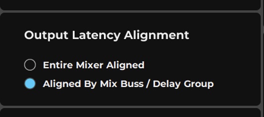
Sets alignment behavior of output I/Os.
Control | Action |
|---|---|
Entire Mixer Aligned | Aligns the entire mixer to one common delay. There will be no separate delay groups. |
Align by Buss/Delay Group | Enables up to 16 user-definable delay groups, each of which can have separate delays. |
Plugin/buss delay compensation is calculated automatically per group. See Appendix B for more on delay compensation.
Individual plugins can be excluded from compensation (Channel > Plugins Rack and Channels > Delay Groups).
Mixer Startup
Previous Session | Loads the last session to its most recent user save. |
Last State | Loads the most recent session to its last state before quitting. This is the file created by the auto-save routine, as described below |
Empty Session | Mixer opens with a blank session. |
History
Every “X” Minutes | Auto-save (on/off) at a defined save interval (3–30 minutes). |
On Scene Update | Auto-save each time a scene is stored, recalled, or modified. |
Sets the rules for automatic saving.
Auto-save Options The mixer stores an unlimited number of auto-saved files. All eMotion LV1 session files use the emo extension.
These files are the same format as user-saved sessions but are stored in a separate folder. Access History files from the LV1 Admin section. Sessions and History files are stored here: Windows: Users\Public\WavesAudio\eMotion\sessions
History files are recalled in the Show window.
Show History Warnings Deselecting this button triggers a “Do not ask me again” selection for History Warnings.
The maximum size of the History folder is 17 GB. Once that size is reached, the oldest files will be deleted in 2 GB increments. Oldest files will be removed first. If Show History Warnings is selected, LV1 will alert you when the History folder has reached 10 GB. This provides ample time to save history files you want to keep. Manually delete History files using the Kiosk.
Lock Mixer
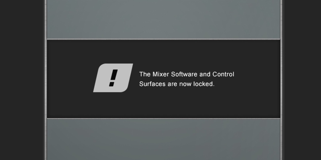
The entire mixer surface—or selected mixer actions—can be locked to prevent unintended structural changes in a session, such as adding, removing, or copying plugins, or changing external patches. Locking these controls does not affect parameters or internal routing. Activate the selected lock options with the Lock button on the right side of the Top Bar.
When Surface is selected and Lock is engaged, there are two ways to unlock the surface:
Fader bank: activate a user key that is mapped to the lock key.
Touch screen: press the Lock button.
You can also lock the application interface, with or without a password. This does not affect the mixer application, only the user interface. Locking the surface also prevents quitting the eMotion LV1 application.
Troubleshooting
Enable Logging
eMotion LV1 constantly logs its activity. Select Enable Logging to provide verbose logging for troubleshooting purposes. Click the Logs button to view or copy the log files. Send these files to Waves technical support if requested.
If more information is needed, a technical support representative may ask you to create and send a comprehensive diagnostics report of the SG operating environment, including certain details of your computer. To scan your computer and create a report, click Diagnostics. You will be presented with a privacy notice. If you agree to its conditions, a diagnostic report will be generated and saved to your desktop. When requested, send this file to Waves technical support.
There is a second tier of troubleshooting in the Admin kiosk Show Patch Warnings When selected, a warning is issued whenever any routing changes are made in the Patch window.
Legacy Send Pan
If you send a mono input channel to a stereo AUX Channel (or IEM) post pan (PSP), the send panner is redundant and so will not be displayed. If, however, you created a session with an older LV1 version using that panner, the session will open in Legacy Send Pan mode ON
When Legacy Send Pan is disabled, all the values of mono PSP panners in a pre-v16 session will be reset, and the redundant panner control will be removed from the interface. This action cannot be undone.
Plugins
Update Plugin List - Scans the system for new plugins.
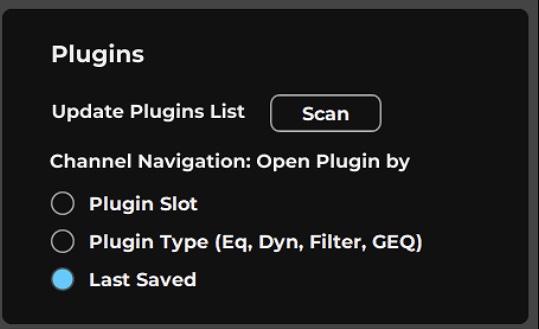
Channel Navigation determines which assigned plugin will open when moving from one channel to another.
Plugin Slot - The plugin slot number is maintained, regardless of the plugin. So, if you’re working on a plugin in slot 3 of channel 5 and you select channel 6, then any assigned plugin in channel 5/slot 3 will open.
Plugin Type - The type of the assigned plugin being edited will open, regardless of the slot number. So, if you are working with an eMO D5 and you move to another channel, the first instance of eMO D5 will open, regardless of the slot number.
Last Saved - Remembers the last plugin viewed on each channel. This information is stored in the session
Local Media Recording
The local media device is useful for recording input channels, stems, and board mixes. Any channel or mix can be patched to the recorder from the Output Route section.
Set Up the Local Media Device for Recording
- Go to the Record Settings panel on the Mixer Settings page.
- Select a drive for recording
- Click Test to see if the drive is fast enough for the job. If a drive is not fast enough, it cannot be used.
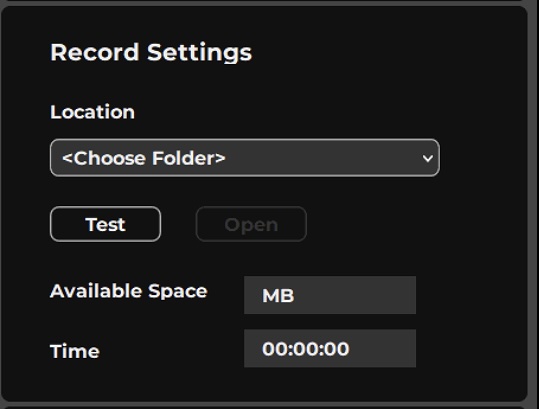
Once the drive is selected, the available space (in MB) and time will be indicated. This time is calculated based on the maximum potential record channels.
For best results, we recommend using drives formatted in the exFAT format. We do not recommend using drives formatted NTFS.
To record console channel output to the Local Media Device From the Patch window
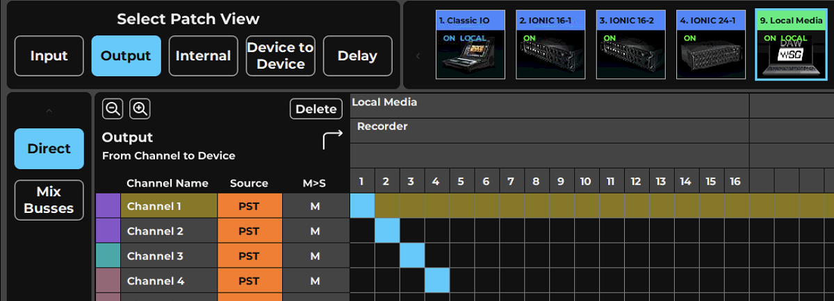
- Open the Patch Window/Output page.
- Select the recorder in the top panel.
- Patch up to 16 console outputs to the recorder. You can patch from console channel direct outs or mix busses.
- Use the REC menu on the Top Bar to start/stop recording.
To record console channel output to the Local Media Device From the Mixer Or Channel windows
- Select a channel you wish to send to the recorder.
- In Mixer Window, Main Route mode or Channel Focus - Route, Or in Channel Window Output section, click on the Rec button to assign to an avaialbe recording channel.
- To assign to a specific recording Channel, from the output Route menu, Select Local Media,and choose the recoding channel you want to assign.
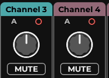
Each console output channel that is patched to a recorder channel displays a small red unfilled circle. This circle becomes solid red during recording. The recorder remains in standby whenever channels are patched to it.
Playback Media Player channels to the console
- Use the Media Player to manage playback from local or USB drive files
- Stereo playback can alternatively streamed from the web browser using online streaming services (requires internet connection to the Network port) note that this will use system resources.
You can assign the Stereo playback using the Patch window or from a Channel Input menu
- Open the Patch Window/Input page.
- Select the Media Player in the top panel / or menu.
- Assign the stereo source to any available input channel.
If Local Media is not available in the Patch, its driver may not have been assigned. If the recorder icon does not appear in the Setup–>System Inventory–>I/O Device rack, use the Network Devices menu to assign it to a device rack slot.
Media Player
The eMotion LV1 Classic console features a built-in media player. You can use it to play music directly from the console for walk-in music, cues, background music, and more, without the need for external audio playback devices.
The media player is connected to the mixer using a SoundGrid ASIO device labeled Recorder, which is assigned in the mixer inventory by default.
Follow these steps to set up the media player and route the sound in the console.
Configure the Media Player
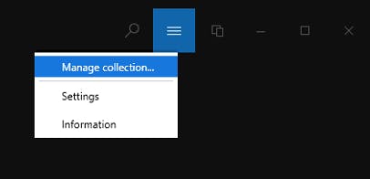
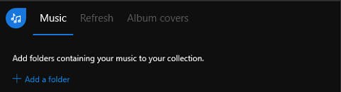

- Connect a USB storage device containing your media files to any of the console’s USB ports.
- Cick the REC button on the right side of the Top Bar and select Media Player from the drop-down menu.
- In the Media Player, click the menu button and select Manage Collection.
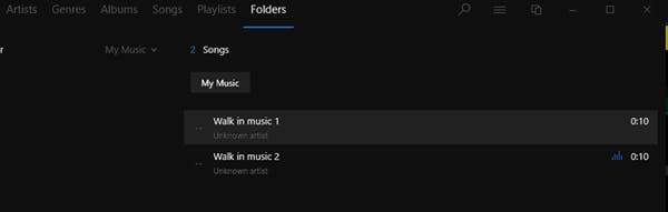
- Click + Add a folder.
- Navigate to the folder containing your music files and click on Select Folder.
- At the top of the media player, click on Folders. The music folder and its contents will appear in the list.
- Select a music file.
Routing the Media Player Into the mixer
- Select the channel that you will use for the media player. You may want to rename the channel.
- Select Flip to Stereo.
- Open the Channel Input Assignment menu again, navigate to Local Media, and select Player 1+2.
Now you can play the media player through the console. Playback is controlled with the media player.
User Interface Settings Page
The U/I Settings page is used to setup indicators and controls, such as meter options and to assign functions to the shortcut user keys.
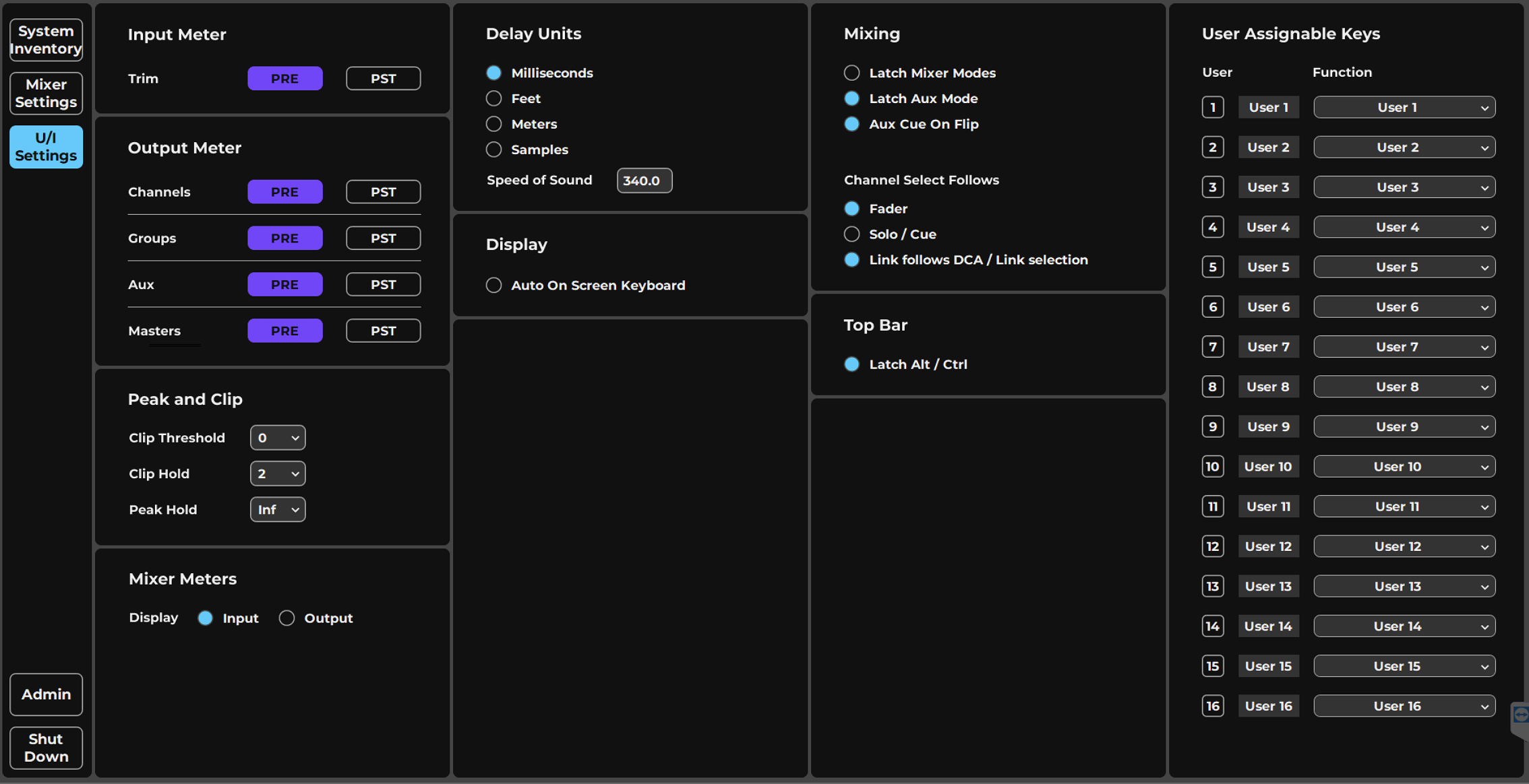
-
Input MetersSelects the metering point at which the input level will be measured. Options: pre-digital or post-digital trim
-
Output MetersSeparately selects output metering points for channels, groups, aux, and masters. Options: Pre-fader or post-fader for each category
-
Peak and ClipClip Threshold sets the level at which a peak light turns red to indicate clipping; setting it below 0 dBFS warns before clipping. Clip Hold and Peak Hold set hold sensitivity. Ranges: Clip Threshold 0 to -28 dBFS, Clip Hold 0 to 5 s, Peak Hold: 0 to 5 seconds.
-
Mixer Window MetersDisplay Input or Output Meters Determines the meter source of the channel strip meters in the Mixer window. Options: Input or output.
-
Delay UnitsSets the unit of measurement for delay-related displays. This setting is provided for convenience only and does not affect delay processing. Delay Units: milliseconds, feet, meters, samples. User-determined speed of sound measurement for use in delay-related calculations, displayed in meters. Default: 340 meters/second.
-
Display OptionsWhen Auto On Screen Keyboard is On, the onscreen keyboard appears when any dialog box that expects text entry is opened. When using LV1 outside of classic an Auto-Scaling function appears to help adjust to the system dispaly settings.
-
Mixing - Modes optionsLatch Mixer Modes Prevents a Channel mode from changing when the Layer selection changes. Aux Cue on Flip Sets the behavior of the Aux mix track Cue buss when the mixer is in the Aux Fader Flip mode. Set to On: If you cue a different channel while in flip and then un-cue the source channel, the cue will return to the aux master channel. Set to Off: The cue will be cancelled upon returning to flip—
-
Channel Select OptionsSets what user action will select a channel. When Fader is selected, touching a fader in the Mixer window will select the channel. When Fader is deselected, touching a fader will not select its channel. When Solo/Cue is selected, clicking solo or cue will also select the channel. Selects link behavior when switching between link groups. (Links apply to faders, pans, and mutes). Set to On: When y
-
Top Bar OptionsLatch Alt/CTRL Keeps the onscreen keyboard Alt or Ctrl keys latched on until they are clicked off. When selected, the ALT and CRTL switches on the Mixer keyboard are in latched mode. Once clicked on, they remain engaged until clicked off. When not selected, these switches are momentary.
-
User Keys AssignmentSixteen user-assignable keys for frequent actions, each assigned from its drop-down Function menu and organized by category. Keys are recalled from buttons on the Top-Bar, or on the Fader Banks dedicated User controls.
User-Assignable Menu Items
Frequent actions can be assigned to 16 user-assignable keys. Assignments are made from the drop-down menu associated with each key. User key assignments are organized by category. You can change the abbreviated name that appears on the recall button by double-clicking it. Use the on-screen keyboard, which is enabled in the Top Bar, if needed. The abbreviated name is stored with the session and will be cleared if the assignment is changed.
To recall a user-assigned key, select a number from the buttons on the left side of the Mixer window. User-assigned buttons are visible in every window as Top-Bar tools. You can also trigger user-assigned keys with the buttons to the left of the assignment menu.
User Keys can be triggered by dedicted controls in Fader Banks, or by remote Apps like MyFOH and mRecall.
Menu Item | Section | Function |
|---|---|---|
Alt/Ctrl | Channel/Mixer windows | Activates Alt or Ctrl modifier keys on the onscreen keyboard. |
Aux Flip Mixer 1 Aux Flip Mixer 2 | Mixer window | The specified aux channel is placed in “Sends on Faders” mode. Sends level is controlled by the channel’s large fader and the master fader controls the aux channel level. |
Clear Solos | Mixer window | Clears solos in all mixer layers |
Copy Channel Preset | Session/Preset menu | Copies channel preset to clipboard. |
Copy Main Mix to Aux | Session/Preset menu | Sends the main mix to a specified aux channel. |
Custom Layer 1 Custom Layer 2 | Mixer window | Opens Custom Layer view on a selected Custom Layer. |
Flip A/B Input channel | Channel/Mixer windows | Switches globally between Inputs A and B. This flips all channels in the session. The prompt, “Are You Sure?” is displayed before you confirm the change. |
Keyboard Launch | Channel/Mixer windows | Calls up the onscreen keyboard. |
Last Track | Channel/Mixer windows | Selects the most recently selected channel. |
Link | Mixer windows | Turns linking on or off. |
Mixer Modes Mixer Modes (Direct) | Mixer windows | Toggles between Mixer 1 and Mixer 2. Moves to selected mode in the selected mixer Top Mode row. |
Mute All | Mixer windows | Mutes the entire console. The prompt, “Are You Sure?” is displayed before you confirm the change. |
Mute Channel | Channel/Mixer windows | Mutes/unmutes a specified channel. |
Next Channel | Channel/Mixer windows | Selects the channel to the right (higher) of the currently selected channel. |
Next Mode | Mixer windows 1 & 2 | Moves to the next Mixer mode Preset. |
Next Scene | Top Bar/Show window | Recalls the next scene from the scenes list. |
Open Session File | Session menu | Opens a navigation panel for selecting a session file to load. |
Paste Channel Preset | Session/Preset menu | Pastes copied preset information and presents a list of channel preset paste options. |
Plugin Bypass | Channel/Mixer windows | Bypasses/un-bypasses a specified plugin. |
Mixer Meter In/Out | Mixer Windows | Toggles Mixer Meters display between Input meter and Output meters. |
Menu Item | Section | Function |
|---|---|---|
Previous Channel | Channel/Mixer windows | Selects the channel to the left (lower) of the currently selected channel. |
Previous Scene | Top Bar/Show window | Recalls the previous scene from the scenes list. |
Recording Start | Top Bar/all views | Starts recording on the local media recorder. |
Recording Stop | Top Bar/all views | Stops recording on the local media recorder. |
Recall Scene | Scene menu | Recalls one scene. Scene select by name. |
Save Channel Preset | Session/Preset menu | Opens a navigation for saving a preset. |
Save Session | Session menu | Saves the current mixer condition and overwrites the existing session. |
Scene Undo | Show > Scenes page | Reverts to previously loaded scene. |
Show Preset Menu | Session/Preset menu | Opens the Preset menu. |
Show Scene Menu | Scene menu | Opens the Scene menu on the Top Bar. |
Spill | Mixer window | Opens the Spill view |
Store New Scene | Top Bar/Show window | Creates a new scene based on the current mixer condition. |
Store Scene | Top Bar/Show window | Stores the current mixer condition to the selected scene. |
Talk | Top Bar | Activates the Talk key. |
Tap Tempo | Setup > Mixer Settings | Tap the recall button at the desired tempo. Result is displayed in the Tempo section of the Mixer settings page. |
TB Preset | Talkback page | Selects one of eight talkback presets. |
Toggle All VGain | Channel/Mixer windows | Toggles all channels between Preset and Local preamp modes. |
Toggle View | Top Bar | Provides direct access to the six mixer windows. |
View Channel | Channel window | Navigates to a channel to open its Channel window. Use the multi-level drop-down menu to select a channel. |
View Plugin | Channel window | Navigates to a channel to locate a specified plugin. Assigned plugins will open the Main Control Section of the Channel window. Non-assigned plugins will be highlighted in the Channel window’s plugin rack. One of each plugin category (EQ, filter, dynamics) per channel can be assigned a shortcut key. |
Chapter 6: PATCH WINDOW
The Patch window establishes connections within the mixer, between the mixer and I/O devices, and between assigned devices on the SoundGrid network. It provides a comprehensive, detailed tool for patching the mixer and presents a wide overview of the mixer’s condition so that engineer can quickly understand its configuration.
Patch Window Sections
-
INPUT viewSelects the Input patch view, displaying a grid of I/Os and mixer input channels for patching microphones and sources to the mixer.
-
OUTPUT viewOne of the five Patch Views selected with the Patch View selector; it filters the channels shown so the grid presents the correct sources and destinations for output patching.
-
INTERNAL viewA Patch View where the top filters select mixer busses rather than I/O devices, used for internal patching.
-
DEVICE TO DEVICE viewSelects the device-to-device view, which displays only the I/O device channels so audio can be streamed between I/Os.
-
DELAY viewOne of the five Patch Views; in the Delay view the left grid filters define rows that are not the usual mixer channels.
-
Classic IO device filterA top filter representing an assigned I/O device; the top filters select which I/O device columns are available to patch. Assigned devices appear on the filter frame from the System Inventory page.
-
IONIC devices filterA top grid filter selecting an assigned I/O device whose channels form columns of the patch grid; all assigned hardware and software I/Os appear on the filter frame.
-
Local Media device filterA top filter for an assigned software/hardware I/O device; its position on the filter frame depends on the patch's purpose, and selecting it makes its channels available to patch.
-
Input A (left filter)A left-side grid filter that defines which mixer input channels make up the rows of the patch grid.
-
Input B (left filter)A left-side grid filter selecting a subset of mixer channels for the grid rows; left filters determine the specific channels available to patch.
-
Patch gridThe central grid where patching takes place; its function changes depending on the patch view and filtering, connecting sources at the top to destinations on the left.
The Patch window is divided into two functional sections that help you patch channels, busses, I/Os, delay groups, servers, and mute groups.
Frame for Filtering Tools: The frame on the left and top determines which channels and devices are needed to execute a particular patch.
Patch Grid: Patching takes place in the central grid. The function of the patch grid changes, depending on the patch view and filtering.
Patch Views
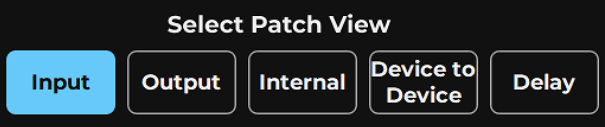
The Patch View selector filters the types of channels to display, based on what kind of patch is to be performed. Once a patch application is chosen, the Selector presents a patch grid with the correct categories of sources and destinations needed to execute those patches. There are five patch views:
Input | Patch between an assigned I/O device and one or more mixer channels. |
Output | Patch between channel outputs and any assigned I/O device. |
Internal | Assign channels to mix busses. Assign control groups, such as links/DCAs and mute groups. |
Device to Device | Patch between assigned network devices. |
Delay | Assign I/Os to delay groups and set delay group timing. |
Filtering Tools
Since the Patch window can connect “anything to anything” within the mixer and between any assigned devices on the SoundGrid network, the number of potential patches is very large. To make patching manageable, sources and destinations are filtered according to the purpose of the patch.
In this example, the source I/O channels (the LV1 Classic) appear at the top of the grid, alongside the recorder. On the left side you see the Console input channels. Here, the recorder is not selected for display, so it does not appear in the patch.
A view is established using the Patch View selector. This filter creates a framework that shows the correct category of channels or devices needed to make a patch, based on its purpose. For example, to patch microphones to the mixer, choose the Input view. This displays a grid of I/Os and mixer input channels. To stream audio between I/Os, use the device-to-device view, which displays only the I/O device channels.
Grid filters (top and left side) are then used to determine which specific I/O channels, mixer channels and busses, or delay, link, servers, and mute group controls will be available to patch from one point to another.
Grid Filters

Each patch view has buttons above and to the left of the patch grid. These buttons select the filters that determine the specific sources and destinations that can be patched in that grid. Grid filters are subsets of the patch views. The Mix Busses filter is, for example, part of the Output Patch View.
The grid filters on the left define the channels that make up the rows of the grid. These are usually mixer channels (except in the Device-to-Device and Delay views).
Columns of channels are defined by the top filters. These are almost always used to select I/O devices (except in the Internal view, where mixer busses are shown).
All I/O devices that have been assigned in the System Inventory page, including both hardware and software I/Os, are displayed on the filter frame. Their position—left, top or both—depends on the patch’s purpose.
The scrolling arrows on each grid filter bar make for easier navigation within a long list of channels or devices.
The Patch Grid
Once a patch view and a grid filter are selected, the relevant channels are displayed in rows and columns. This (the Patch Grid) is where filtered channels, busses, and control information are patched.
Patch Grid Zoom Tools
Zoom in and zoom out buttons enable detailed views or broad overviews of the patch grid.
Delete Patch
Pressing Delete will remove all the patches from the current Patch View Tab,
Grid Row and Column Information
For Input, Output and Internal views the Rows will represent Input channels or Mix Channels. In the Device to Device view Rows will represent device IOs, and in the Delay view Rows represent Delay Groups.
For Input, Output, Devcie to Device and Delay, Columns represent the Device IOs. While in Interal view they represent mixer busses, functional groups liek Link and Mute or Server assignment.
I/O Device Channels
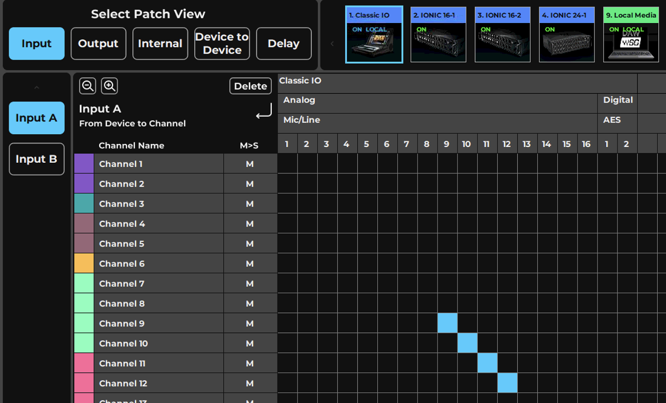
Hardware and software I/Os are represented by icons, which appear in the horizontal and/or vertical grid filter bars, depending on the patch view. Click on a device icon to display its I/O channels, and additional applicable information. Any number of available I/Os can be expanded simultaneously to reveal their channels.
- Name of I/O device or driver. Matches the device icon in the Inventory.
- Format: Analog or digital.
- Connector: Mic, line, phones, AES, S/PDIF, ADAT, MADI, ASIO, etc.
- Channel Number
Next to the device name is a series number. This indicates the device’s slot number in Device Rack A (1–8) and Device Rack B (9–16) (Setup > System Inventory > Device Racks).
Mono and Stereo Channels
- Input channels can be changed from mono to stereo by double-clicking on the M or L/R buttons. When a mono channel is flipped to stereo, its name appears on both the left and the right sides.
- When a channel is flipped from stereo to mono, the left channel patch becomes the mono patch.
- Mono/Stereo status reflects the current state of the channel and can be changed only on Input channels.
Patch Point
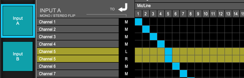
A patch is created at the intersection of horizontal and vertical grid lines. Select patch points individually or draw a straight line vertically, horizontally, or diagonally. Click again on a patch to remove it.
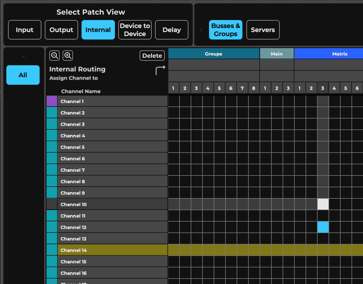
- A valid patch is blue.
- A yellow highlight identifies the selected channel
- A stereo channel can accept signals from two independent mono sources.
- A red patch indicates that the patch point was taken from you, most likely by the manager.
- Shared I/O channels are shown as yellow columns.
Illegal patch possibilities are grayed out in the grid.
Channel Name
To change a channel’s name, double-click on its Name field and type up to 12 characters. The name is also displayed, and can be changed, in the Mixer channel strip and in the Top Bar. Use tab to move to the next channel when renaming, and shift-tab to move to the previous channel name cell.
You can color-code the channels to better organize the view. Channel coloring is reflected in all views.
- In the Preset menu, select Set Channel Color or click the colored cell to the left of the mixer channel name in the patch. This opens the Color Picker.
- Select a color from the palette.
- Use the left/right arrows to apply colors to additional channels.
Mixer Inputs
This is the only patch view where signal flow is from top to left (I/Os on top to input channels on the left). To avoid confusion, it is convenient to name the channels before patching.
Input Patch Behavior
- Inputs A and B can patch to the same I/O channels or to different I/Os.
- An I/O device channel can be patched to more than one mixer input channel.
- A stereo channel appears as two independent channels (L and R) with the same name.
- The two sides of a stereo channel are patched separately, whether from a single stereo I/O channel or from two different mono channels.
Mixer Outputs
A mixer channel or buss can be patched to any available I/O that has been assigned to eMotion LV1.
The Output view has two grid filters: Channel Direct outs and Mix Busses out. Mixer outputs are displayed on the left and assigned I/O device channels are displayed along the top.
Each channel or buss can output from one of four sources, indicated by the multi-colored buttons. To select a source, click on its button:
INP | Green | Before all processing, post input gain |
PRE | Purple | Pre-fader, post-processing |
PST | Orange | Post-fader, post-processing |
fader | Turquoise | Post-fader, post-processing, post-panner |
On a stereo buss, source settings apply to both left and right channels. An I/O device can receive only one source signal.
Internal Routing
The Internal Routing view patches within the mixer; there is no patching to external devices. Each of these patches can be made on a channel-by-channel basis in other windows. The Internal Routing view, however, provides an overview of mixer assignments and lets you quickly establish many patches at once. There are two patching frames: (1) Busses & Groups and (2) Servers.
Busses & Groups patches these mixer channels (Channels, Groups, FX, Mon, Main, and Matrix) to busses (Groups, Main, Matrix, Link, and Mute Groups).
The scope of these internal assignments is set in the Mixer Configuration window (Setup > Mixer Settings > Mixer Configuration). Larger mixer configurations include more groups, aux channels, and busses.
A channel can patch to any buss, but a buss cannot patch to itself or to any buss that is earlier in the signal flow.
Assigning Multiple Servers
Servers provides an overview of server group assignments.
This is a convenient way to patch a server to multiple channels at once, as shown here. This is a quick way to understand how servers are assigned in the mixer and to rebalance server distribution for maximum DSP power.
Device-to-Device
The Device-to-Device patch view is like a network patch bay. It enables all devices assigned to the mixer to patch with one another. This view does not allow patching to or from the mixer.
Device-to-Device Patch Behavior
All I/O devices that are assigned to the LV1 inventory appear in the Device-to Device view. A device can patch to any other assigned device, but not to itself.
Delay Groups
Delay groups are collections of I/O device channels whose timing can be controlled as a unit. These are not audio busses, but rather a means of managing the delay of one or more grouped I/Os. A delay group typically consists of several I/Os. An individual I/O can belong to only one delay group.
Delay groups serve two functions:
- Coordinate plugin and buss latency compensation to busses routed to selected I/Os.
- Apply the same delay to all I/Os in a group.
The mixer’s 16 delay groups are listed on the left side of the patch grid, along with their user-defined (Custom) delays. The total latency of the delay group (processing delay + custom delay) is also shown.
Delay groups can also be established in the Channel window Direct Output list, by selecting an assigned destination the lower panel displays the Delay settings including Delay Groups assignment . Please refer to Appendix of this user guide for a detailed description of eMotion LV1 delay management.
Chapter 7: SHOW WINDOW
Sessions, scenes, and recall- safe parameters are managed in the Show window. Overall mixer parameters, snapshots of specific program changes, scene scope and recall safe are all set here.
Sessions Page
The Sessions page is where you save, load, and name the session files that contain all mixer settings. The session includes all the channels and mix busses processing settings, levels, internal routing and IO Device assignment and patching, all the scenes data, and the custom settings.
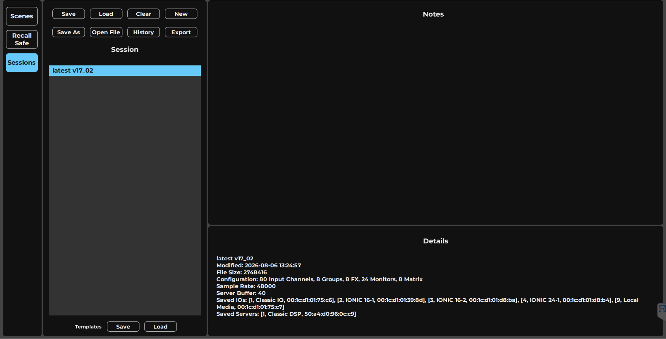
-
Session Tab
-
SaveSaves the session. If the file has not been saved before, Save creates a new file; otherwise it replaces the existing file. Sessions are normally saved to the console's D drive sessions folder.
-
LoadLoads the currently selected session from the Sessions list.
-
ClearClears the Sessions list. All sessions are removed from the panel but remain in the Sessions folder.
-
NewOpens a blank session, loading the three EMO plugins with their default values. The new session does not appear in the Sessions list until it is saved.
-
Save AsSaves the current session under a different name, useful for preserving channel information before changing the mixer configuration.
-
Open FlieLoads a session that is not currently in the Sessions list. Opening a session from a USB drive copies it to the Sessions folder on the console's internal drive; you cannot run a session from a USB drive.
-
HistoryOpens a browser showing all History files, named with the session name and a date/time timestamp. These files are stored in the History folder on the console's D drive.
-
Sessions ListShows the sessions LV1 has loaded (not necessarily all sessions in the folder). Used to select, copy, and load sessions; color codes indicate each session's status.
-
Template SaveCreates a session template from the current session. A template loads all mixer parameters except the I/O inventory.
-
Template LoadLoads a session template. A loaded template does not appear in the Sessions list and is initially named 'Untitled'; it should then be saved as a session under the desired name.
-
ExportExports the selected session (as a copy) to an external USB thumb drive. This lets you, for example, move a session to another LV1 Classic.
-
NotesA large notepad used for entering details about the session, the venue, or anything else you want to write.
-
Session DetailsDisplays session information including: Session name, modification date and time, and size, as reported by the operating system Configuration, sample rate, server buffer Saved I/Os, saved servers
Sessions List
The Sessions list shows the sessions that LV1 has loaded, not necessarily all the sessions in the Sessions folder. It is used to select, copy, and load sessions.
If you clear the list, all the sessions will be removed from the panel, but they will remain in the Sessions folder.
An example: Let’s say you hire an LV1 Classic from a sound rental company. When you open the Sessions page, the list is filled with sessions that mean nothing to you—session names that you don’t want to clutter up your list. Clear the list and it will be empty. Copy your sessions from your thumb drive. When you load a session, it will populate the Sessions list. The previous user’s sessions reside safely in the Sessions folder.
Color codes indicate a session’s status as follows:
- A selected session is highlighted blue (whether it is the recalled session or not).
- A highlighted session is not active until it is loaded.
- If the current session is not selected, it will be highlighted yellow, and the selected session will be highlighted blue.
Notes associated with the selected session are shown in the Notes section.
Loading a Session
Load a session from the Sessions list or from the Preset menu.
Loading a Session From the Sessions List
The Load command loads a session from the selected session in the Sessions list. Open loads a session not currently in this list. Opening the session from a USB drive copies the session to the Sessions folder on your console’s internal drive, after which LV1 will not search the USB drive. You cannot run a session from a USB drive.
Loading a New Session
Click the New button to open a blank session. This loads the three EMO plugins with their default values. Patching, inventory, and any other information that is stored with a session is not removed. The new session will not appear in the Sessions list until it is saved. Use Save to save the session and assign a name.
Loading Sessions from the Preset Menu
The Preset menu is located on the left side of the Top Bar. It is used primarily to manage channel presets, but it also provides a quick way to load and save sessions and templates.
Resolving Load Errors
If there are differences between the session being loaded and the current mixer size or inventory, the mixer must reconcile this mismatch.
Example 1
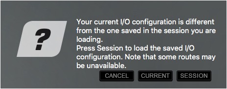
The I/O inventory of the saved session does not match the current mixer inventory.
Whenever the saved session’s I/O inventory is not the same as that of the mixer, there is a chance that certain channels cannot be supported. If, for example, the session calls for a 128-channel MADI device while the I/O in the same slot is an Ionic 16, it will be difficult to provide the session with the channels it needs.
The Session Load routine provides two strategies for loading sessions onto mixers that are mismatched.
Option A: Session – The session loads completely, even though the device inventory does not match the session. Devices called for by the session and missing from the rack slot will appear as not available (N/A). The session’s patching does not change, but the I/O channels of unavailable devices are not accessible and are colored red.
Option B: Current – The saved session loads into the existing I/O inventory. The saved session is replaced with a new one that reflects the current device inventory. The mixer searches each rack slot for an assigned device that will match the needs of the session. The device in the slot does not need to match precisely what the session requests, but it must have sufficient I/O channels.
System Inventory is catalogued by slot, not by rack, so an appropriate device must be found in the same slot specified by the session. The original session’s patches for the I/O in a specific slot will be patched depending on the current channel count. For example:
- The session calls for an Ionic 24 device in slot 1 and another in slot 2 (16 I/O channels each).
- The current inventory has 64-channel I/Os in slots 1 and 2.
- When you load the session into this inventory, all patches will be intact. The first 12 I/O channels from each interface will be patched, but the remaining channels are unused.
Example 2
The saved session has more channels than does the current mixer configuration.
In this case, the session calls for 64 channels, while the system inventory has only 32. If the mixer can be enlarged to 64 channels, the session will load without incident. Otherwise, the last 32 channels will be deleted and the settings associated with those channels will be lost. In either case, it’s important to save a copy of the session before proceeding.
Missing Server
If you load a session that requires a server that is not present in your inventory, you will be asked to reconcile the session with the inventory. The server may be disconnected, off, or not in working order. Check these possibilities and return the server to its slot in the Servers Rack. If the original server is not available, replace it with a comparable server, in the same slot.
Session Will Not Load—Session Converters
If a session will not load, there’s a good possibility that the session converters are not aligned with the session that’s being loaded. To remedy this problem, follow these steps:
- Enter the Kiosk.
- Launch Waves Central and log in, if necessary.
- Go to Install Products and click on All Products at the top.
- In the Search field, type Session Converter and choose Session Converter.
- Click Install.
- Re-launch eMotion LV1 Classic and load your session.
If your session still does not load, contact Technical Support.
Templates
A template is a mixer session based on a previous session or a factory preset. It loads all mixer parameters (except the I/O inventory), which facilitates moving projects between mixer systems whose inventories are not identical.
A loaded template does not appear in the Sessions list. It will initially be named “Untitled.” Once loaded, a template should be saved as a session under the desired name. It will then appear in the list.
Use the Templates/Save button to create a session template from the current session.
Templates are filed in the Templates folder next the the sessions folder. Can be accessed from the Advanced Kiosk options.
Saving a Session
If a file has not been saved previously, Save creates a new file. Otherwise, it replaces the existing file. A session is normally saved in the console’s D drive folder, which is accessed in the Kiosk (Users\Public\Waves\eMotion\sessions).
A navigation window enables you to store the file anywhere.
The Sessions folder includes two sessions: “CurrentLV1.emo” and “CurrentLV1.emo-journal.” These are the recovery files. Do not delete or move them.
Auto-Saving Sessions
The mixer can save sessions automatically, either at user-defined intervals or each time scenes are saved or recalled. Auto-save settings are managed in the Mixer Settings page (Setup > Mixer Settings > History). To prevent mishaps, eMotion LV1 does not delete auto-saved files. This can result in a large number of files, but it provides access to all session information saved throughout a project.
There are three Auto-Save settings
No Auto-Save | No automatic saves; no History files are created. |
Auto-Save | New History files are created at user-defined time intervals. |
On Scene Update | A new History file is created each time a scene is recalled or stored. |
Click the History button above the Sessions list to open a browser that shows all History files. They are named with the session name and a date/time timestamp. Locate a session and open it. These files are stored in the History folder on the console’s D drive and can be accessed via the Kiosk (Users\Public\Waves\eMotion\history).
Saving a Session After Mixer Configuration Has Changed
It’s possible to change the number of mixer channels at any time, depending on the scope of your license. If the number of channels in the session has been reduced since the last time it was saved, this prompt will appear when you save.
Removing channels clearly results in a loss of channel information. A normal Save at this point would eliminate all settings from the removed channels, since it overwrites the session file. To preserve that information, save the session under a different name—before you change the configuration—unless you are absolutely certain that you want the mixer to be set to a smaller size.
If the new session has the same number of tracks and calls for the same, or similar, I/O inventory, the new session will load immediately. When working on the same mixer repeatedly, this is usually the case.
Set mixer size via Setup > Mixer Settings Page > Mixer Configuration
Scenes Page
A scene is a snapshot within a session, used to change presets during a performance. Use the Scenes page to create, recall, and save scenes in a session. A session can contain up to 1000 scenes.
The types and number of selector buttons on the Scope and Recall Safe panels reflect the Mixer configuration, which is set in the Mixer Settings page. With smaller configurations, some buttons will be grayed out.
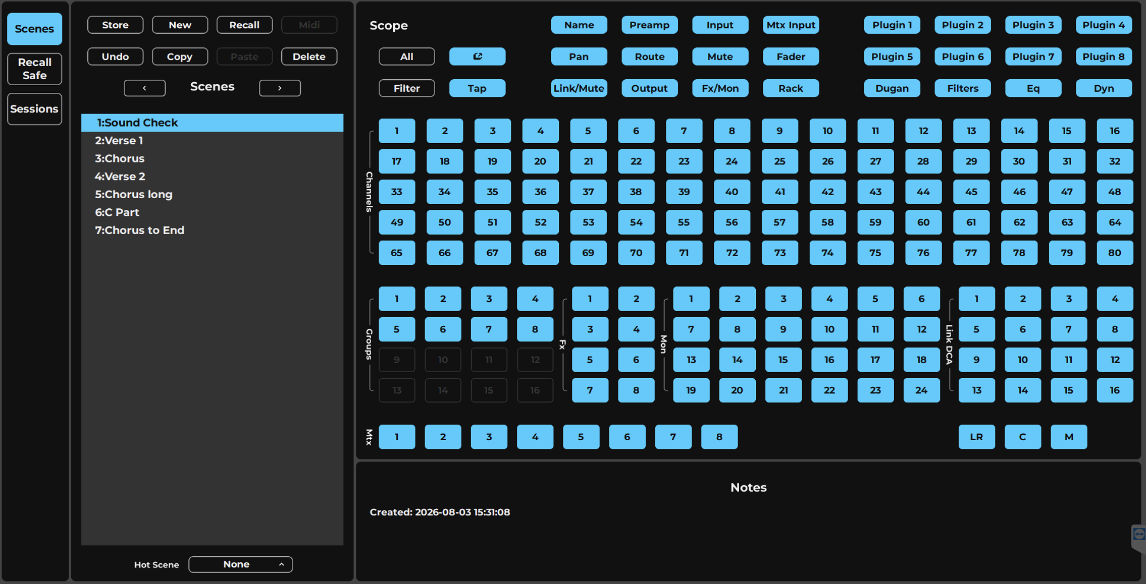
-
StoreUpdates the current snapshot and scope parameters with the current mixer condition. Replaces the existing stored scene.
-
NewCreates a new scene, based on the current preset and scope settings. This makes a new scene from the current one and serves as a “Save as” function.
-
RecallRecalls the selected scene. The name of the recalled scene is displayed in the Scenes section of the Top Bar.
-
UndoUndoes the previous change. One level of undo is available.
-
CopyCopies the selected scene to the clipboard. This can then be pasted back to the Scenes list as a copy.
-
PastePastes the copied scene to the Scenes list.
-
DeleteDeletes the selected scene (which is not necessarily the current scene). A deleted scene can be recovered using the Undo function.
-
MIDIEnables “scene follow program change” events for remote-controlling scene changes. A red lamp indicates that MIDI program changes are enabled.
-
Scenes ListA list of all scenes associated with the current session.
-
Scope SelectorsSets which functions, channels, and busses will be affected when a scene is recalled.
-
All/None SelectorSelects or deselects all functions, channels, and busses in the Scope list.
-
Channel Parameters SelectorsSpecify which channel parameters can be altered by a scene change. If a control is not included in the scope of the scene, its parameters will not change on any channel. Certain selectors provide more options via popup windows.
-
Input Channel, Buss, and Link SelectorsSpecify the channels, busses, and control groups included in the scope of the scene. If a channel, buss, or link is not included in the scope of the scene, then no parameters will change for that channel.
-
Hot Scenes ListUser-assigned snapshots that are quickly accessible for recall. Up to eight Hot Scenes can be recalled from the Scenes menu and user-assigned keys.
-
NotesEach scene has a dedicated notes section.
Scene List
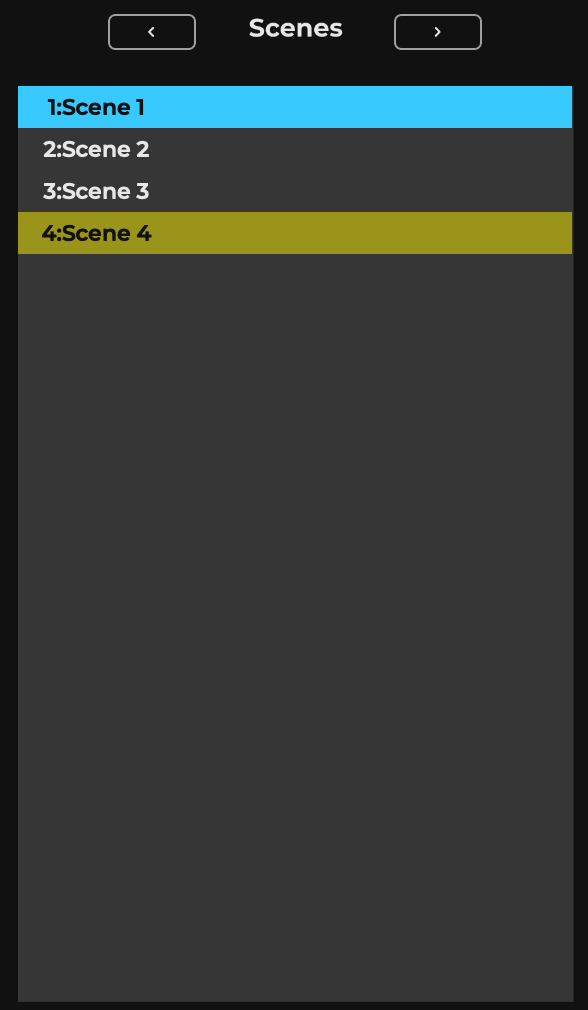
The Scenes list behaves in the same manner as the Sessions list as follows:
- A selected scene is highlighted blue (whether it is the recalled scene or not). A highlighted scene is not active until it is recalled.
- Notes associated with the selected scene are shown in the Notes section.
- If the current scene is not selected, it will be highlighted yellow, and the selected one will be highlighted blue.
Above the Scenes list are two arrows. Use them to recall scenes lower or higher than the current one in the Scenes list. Clicking an arrow loads the scene immediately.
Storing Scenes in the Scenes List
This saves the mixer condition to a scene. Typically, the current mixer settings are stored to the current scene. However, if a scene other than the current one is selected, you will be given two options:
- Store the parameters in the current scene.
- Store the parameters in the selected scene. This replaces the contents of the selected scene.
Scenes, unlike sessions, are not separate files. They are embedded in the sessions, so there is no “Save as” function. Use New to create a new scene, which you can then save.
Recalling Scenes From the Scenes List
Select a scene and click Recall.
Changing the Order of the Scenes List
A scene’s place in the Scenes list determines its recall number, so it’s important to be able to change its position. There are two ways to do this. Change its position by:
- Dragging the scene to a new location.
- Copying the scene with the Copy button and pasting it in the desired position using the separator line. If the separator line is not used, the copy will be added to the bottom of the Scenes List. Double-click on the scene to change its name.
Top Bar Menu
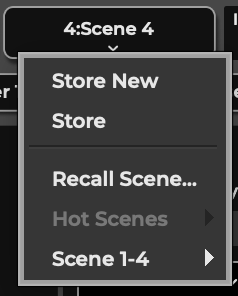
Storing a Scene with the Top Bar Scenes Menu
The Top Bar Scenes Menu is located on the right-hand side of the Top Bar. Here you can store the current mixer condition to the current scene. Choose Store New to create and name a new scene. New scenes are stored at the end of the Scenes list.
Recalling Scenes with the Top Bar Scenes Menu
Scenes can be recalled from the drop-down Scenes menu on the Top Bar. Unlike the Scenes list, a scene selected in this menu is recalled immediately.
Recall Scene recalls a scene based on its position in the Scenes List. Use the up/down arrows to navigate the list or enter the index number directly.
Scene 1–32, etc. is a drop-down menu of all scenes in the session. Scenes are displayed in the order of the Scenes list. Selecting a scene opens it immediately. A session can have up to 1000 scenes.
Hot Scenes
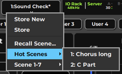
Hot Scenes are user-selected scenes that are quickly accessible for recall.
At the bottom of the Scenes list is a menu of Hot Scene assignment positions. Use this menu to assign the selected scene a Hot Scene position.
Hot Scenes are recalled from the Scenes menu on the Top Bar. The scene’s name and Hot Scene position are shown. The scene is recalled immediately.
The Scenes list on the Top Bar can be controlled with MIDI program changes. Use the MIDI control panel to set up Follow Program Change or Generate Program Change commands (Setup > System Inventory > Controls > Device Control Panel). The MIDI button is illuminated when scene recalls are under MIDI control.
Scope Section
The Scope section sets which functions, channels, busses, and control groups will be affected by scene changes. Scope is set for each scene, not by session. Scope selections are divided into three categories:
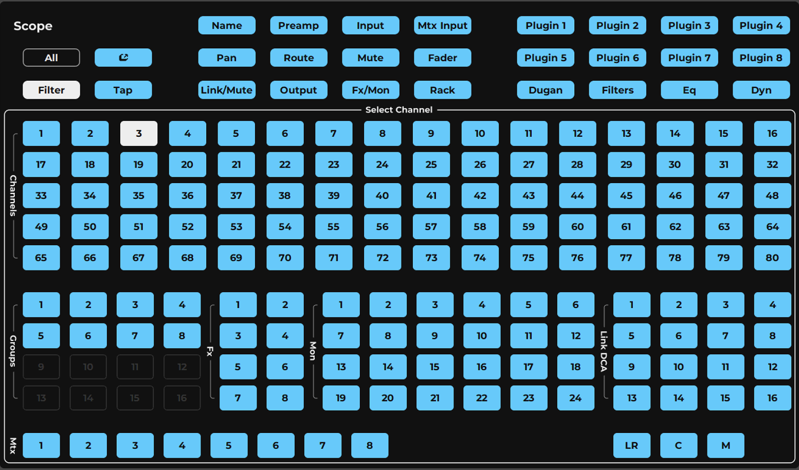
-
ALL / NONEResets the Scope selection so that either all parameters and channels are within the scope of the scene, or none are.
-
GlobalChannel parameterSets which channel parameters (Name, Preamp, Input, EQ, Dyn, Filters, Rack, Plugins, etc.) are within the scope of a scene. These settings apply equally to all selected channels.
-
Select Channel gridSets which input channels are included in the scope of the scene; a deselected channel does not change on scene recall, regardless of the Function settings. The number of channels shown reflects the current mixer size.
-
Channel FilterPer Channel Parameter Filter setting mode. Once pressed selecting a channel button will bringup the channel filter that affects that specific channel only.
Channel parameter selectors Input channel selectors Buss and link selectors The color of a button indicates the channel’s scope status.
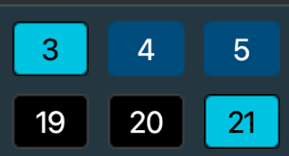
- A light blue button represents a parameter that is within the scope of the scene.
- A black button represents a parameter that is not within the scope of the scene.
- A dark blue button indicates that the parameters within that specific channel have been edited.
Global Channel Parameters

Sets channel parameters that are within the scope of a scene. These settings apply equally to all selected channels.
Name | Channel name |
|---|---|
Preamp | 48V, preamp level |
Input | Trim, phase |
MTX Input | Matrix input faders |
FX/MON | Send levels, on/off, pan, route |
Click the XF/MON button to open a panel for selecting any FX or MON buss. | |
Pan | All pan/balance/rotate controls |
Route | Internal routing: group, matrix, links, mute groups, main (L/R, C, M) |
Mute | Change state: on/off |
Fader | Change value |
Mute GRP | Mute group assignments |
Output | Delay (channel out, not group), on/off delay, gain |
Windows | Floating window configuration and content |
Tap Tempo | System tempo |
Plugins | Plugins (including assigned dynamics, EQ, and filters processors) can be included or excluded from the scope of the scene. |
Dugan | Auto, weight fader, override, group |
All/None Select: Resets the Scope selection to “all parameters/channels are within the scope of this scene” or “no parameters/channels are within the scope of this scene.” Rack: When On, rack processing on/off is in the scope of the scene change.
Dyn/EQ/Filters: When selecting a Dyn/EQ/FLT state in Scene or Recall Safe, it will override the state in Plugins 1-8. Example: If EQ is set to Off, it will be out of scope, even if Plugins 1-8 are set to On (in scope), and vice versa.
Select Scope of Aux Channels, Link/DCAs, and Mute Groups
Click the FX/MON selector button to open an extended Scope panel.
This enables you to select specific FX/MON sends.
Click the Link/Mute button to set the scope of Link/DCA and Mute Groups assignments and Mute Group activation.
Channel Select Section
Input Channels: Sets which input channels are included in the scope of the scene. A deselected channel does not change with a scene recall, regardless of the Function settings. The number of channels in the Scope section reflects the current mixer size.
Busses and Links: Sets the busses and control groups that will or will not be included in the scope of the scene. Selections include Input channels, Groups, Auxes, Matrix, and Main Outs. Links/DCAs can also be included in the scope of the scene.
Filter Within Channels
You can set the scope of all parameters, per channel. The Channel Filter lets you select a channel, buss, or control and then define the scope within that channel. When a selected channel changes with a scene change, specific parameters are executed or ignored. This provides much more detail when defining scope.
To filter the scope of a channel, follow these steps:
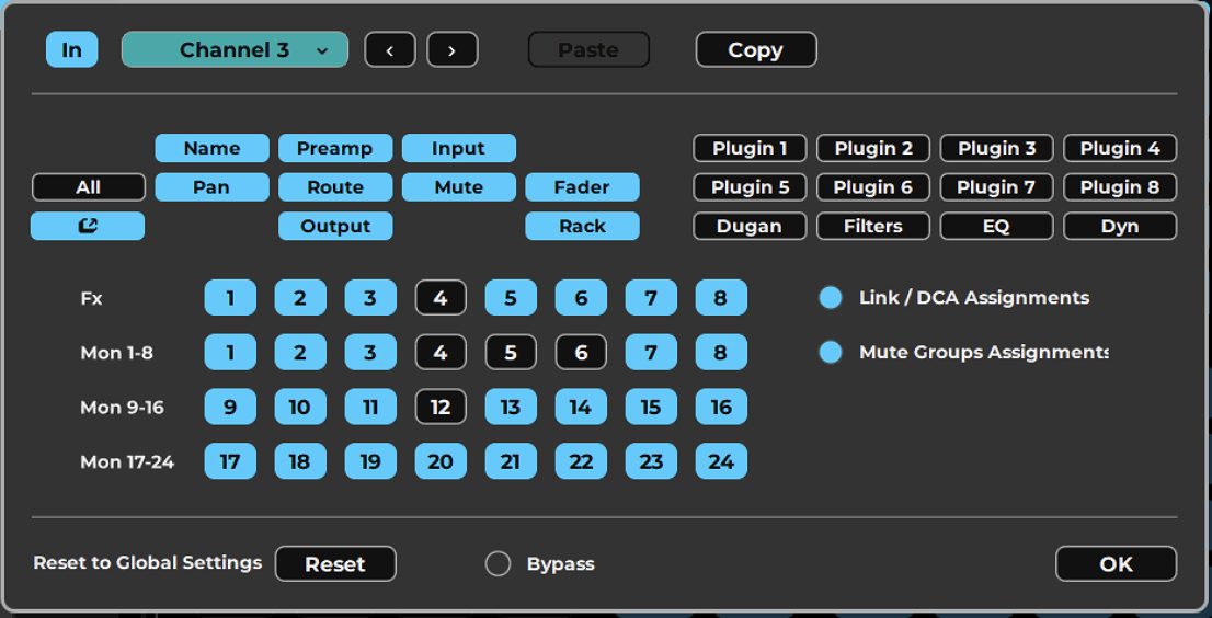
-
Reset to GlobalPart of the Channel Filter panel used to define the scope of parameters within a selected channel; resets that channel's filter back to the global scope settings.
-
OKConfirms the channel filter selections and returns to the main Scope window.
-
Channel parameter selectorsSelects which parameters (Name, Preamp, Input, Pan, Route, Mute, Fader, Output, Rack, Dugan, Filters, EQ, Dyn, Plugins 1-8) are within the scope for the chosen channel, giving detailed per-channel control over what a scene change executes o
-
Navigate Channelsmove to next or previous channel.
-
Copy / PasteCopy and Paste the Chanenl scope setting to a different channel.
-
In ScopeActive in Scope indication
-
Bypass Channel ScopeBypass the channel specific scope
- Click on the Filter button at the top-left corner to enable per-channel filtering.
- Select the channel for which you want to allow detailed filtering. The Filtering panel appears.
- Use the selection buttons to set the scope of FX/MON busses, Channel Parameter controls, Link/DCAs, and Mute Group assignments. Only parameters that are logically assignable are shown in the window.
- Use the left/right arrows or the channel menu next to the channel name to navigate among the channels.
- Use the Bypass button to temporarily deselect all choices within the window.
- Once you have made any changes in the window, the Reset to Global button will appear. Click the button to clear all selections you have made in the panel.
Click OK to return to the main Scope window.
Recall Safe Page
The Recall Safe page prevents changes to specified channels, busses, and functions during a scene change. An item in Recall Safe mode is exempt from changes. Recall Safe is set for an entire session, not by scene.
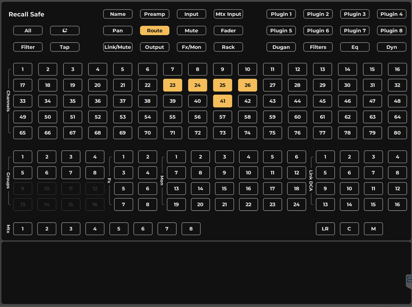
Once Recall Safe is set for the parameters and channels of a session, scene recalls will not affect their settings. The controls in the Recall Safe panel are identical to the Scope section controls. Selections are organized by channel functions and plugins, input channels, groups and controls.
Audio channels and busses can be set to Recall Safe from this panel, as well as from the drop-down Preset menu for that channel. As with the Scope page, there is an All/None button that selects and deselects all parameters and channels.
Select Scope of Specific Aux Channels, Link/DCAs, and Mute Groups
Click the FX/MON selector button to open an extended Scope panel. This enables you to select specific FX/MON sends.
Click the Link/Mute button to set the scope of Link/DCA and Mute Groups assignments and Mute Group activation.
Channel Recall Safe
Individual channels can also be set to Recall Safe from their Preset menu. This is the same as selecting the channel in the Recall Safe section, but may be more convenient at times. These selections are indicated in the Recall Safe page and the Session Name field in the Top Bar.
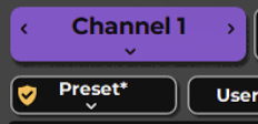
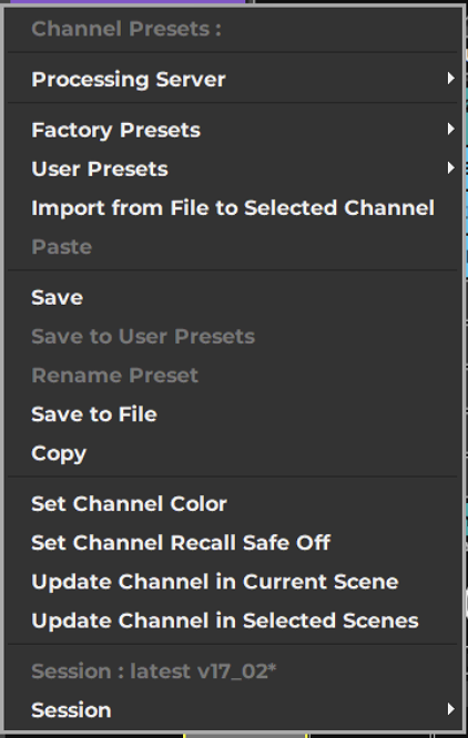
Recall Safe is also indicated per channel in Mixer windows right under the channel name, by a small shield icon.
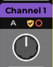
Channel Recall Safe Scope
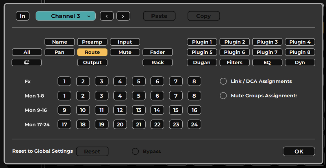
Individual Channels can be set to be partially safe by the per channel Recall Safe Filter. This setting will only effect one channel. The chanenl filter can be copied between channels, and uses a similar intreface as the per Channel Scene Scope Filter.
Preamp Recall Safe
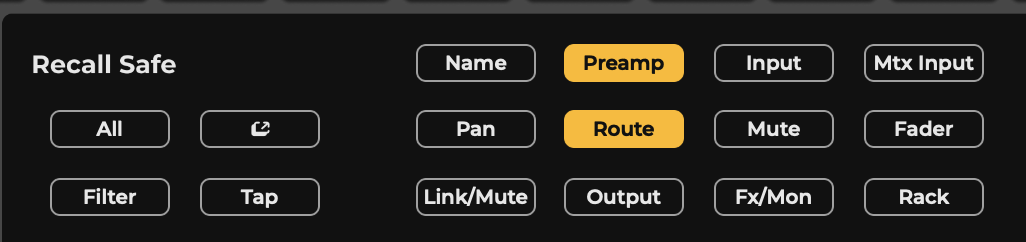
To ensure that I/O device preamp parameters are not changed when a scene change occurs, select Preamp in the Recall Safe page. This is a global command that protects all preamps on Recall Safe selected channels.
Recall Safe for Specific Plugins
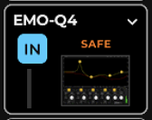
The Recall Safe page determines if specific plugin rack positions on specified channels will change when scene changes occur.
Recall Safe Plugin On/Off, on the other hand, prevents a specific instance of a plugin from changing. This drop-down menu item is located at the bottom of the Plugin menu of a specified plugin. The menu item indicates if the plugin is set to Recall Safe.
There is also a small “Safe” indicator on the plugin icon.
Other plugins in the rack are unaffected and can be set individually to Recall Safe.
Chapter 8: SIGNAL FLOW
LV1 Classic Signal Flow diagram provides and overview of the signal flow in concept. As this is a digital mixer the actual internal signal flow is an array of sample storage being saved and manipulated in a short time before send back to IO device for convertion.
Use this diagram to understand the routing possibilities and limitations.
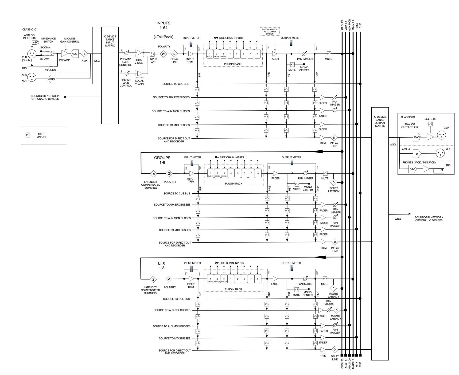
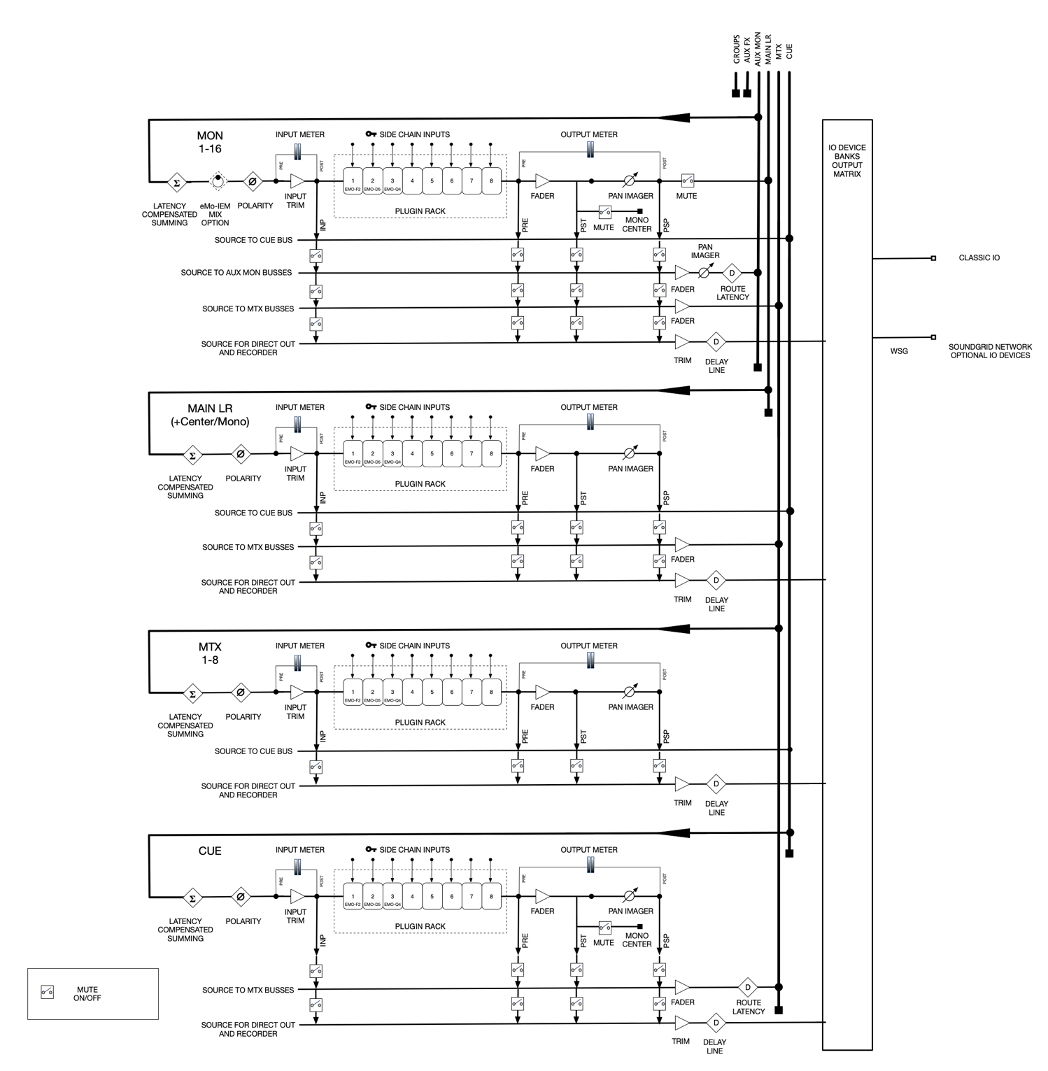
Chapter 9: APPENDIX
A: Fader Bank
The eMotion LV1 Classic fader bank maps to the LV1 touchscreen control surface. The 16+1 motorized faders and multipurpose encoders provide control over mixing functions and plugins parameter contorls.
-
Channel Select ButtonClick the User button to toggle between Channel (default) and User-Assigned Keys.
-
Four-line Scribble Strip
-
Rotary EncodersControl Pan, Gain, or Plugin edit mapping.
-
Solo/Mute
-
16+1 100 mm Motorized Faders
-
Mixer Layers 1–8 Selector
-
Encoders ModeSelect Pan, Gain, or Plugin edit mode.
-
ShortcutsUser-assignable.
-
Fader Alternative ModesCustom/Spill/Sends on faders.
-
Touch and TurnMaps to selected control for immediate access.
-
Tempo Tap Pad
1 | Channel Select Button Click the User button to toggle between Channel (default) and User-Assigned Keys. |
2 | Four-line Scribble Strip |
3 | Rotary Encoders Control Pan, Gain, or Plugin edit mapping |
4 | Solo/Mute |
5 | 16+1 10mm Motorized Faders |
6 | Mixer Layers 1–8 Selector |
7 | Encoders Mode Select Pan, Gain, or Plugin edit mode |
8 | Shortcuts (user-assignable) |
9 | Fader Alternative Modes Custom/Spill/Sends on faders |
10 | Touch and Turn Maps to selected control for immediate access. |
11 | Tempo Tap Pad |
Fader Bank Controls | |||
Channel select buttons (Function changes with controller mode) | Channel Select Mode (default) Click to select a channel. An unselected channel’s button is the same color as the corresponding channel on the LV1 touch screen. User Mode (User button on) The 16 channel buttons are mapped to the 16 user-assignable keys. Edit mode maps channel faders and encoders to the controls of the selected channel’s plugins. Flip Mode The Select buttons and the first row of scribble strips are used to select the aux destination. (Flip button on): Buttons 9–11: select destination layer (FX 1–8, MON 1–8, MON 9–16) Buttons 1–8: select destination channel within an Aux layer Once you select an aux destination, the faders flip. Large faders are sending to the selected aux. The blinking Flip light indicates the mode. | ||
Scribble strip (Display changes with controller mode) | The Scribble Strip is a four-line display that provides feedback about channel condition. In Channel Select Mode: Selected channel is indicated with a white bar. Channel name, default or user-named Channel input source Function of the rotary encoder (preamp gain or channel pan, or plugin edit) In User Mode, the user-assigned function is shown at the top of the scribble strip. Use the channel button to apply the key. In Edit Mode, the encoders are mapped to the controls of the selected plugin. When a control has a has a discrete switch (e.g., on/off, mode, bypass) and a variable control (e.g., gain, frequency, threshold), the variable control is on the bottom row. Plugin controls are arranged in pages. Use the layer buttons to move between controls. In Flip Mode, Aux destination channels are identified on the top row. | ||
Rotary Encoders | A rotary encoder controls the channel’s pan or input. It also maps to a specific plugin control when in the Edit mode. In the Edit mode, the Encoder buttons to toggle between gain or pan (default). This toggle affects all channels in the layer. The value and label of this control are displayed on the scribble strip above. The encoder’s function is set in the Encoder section. | ||
Solo/Mute | Activates CUE or SOLO, depending on LV1 Cue channel settings / activates MUTE | ||
Channel Faders / Master Fader | 16+1 touch-sensitive motorized faders Master fader mapping is set in the Fader Bank contol panel. | ||
Mixer Layers selectors | Click a button to select a mixer layer. | ||
Encoder Modes | Channel 13: unused Channels 14–15: previous/next page Selects function of the rotary encoders. Channel 13: unused Channels 14–15: previous/next page Channel 13: unused Channels 14–15: previous/next page Pan (lavender) By default, the encoder knobs are mapped to channel pan. Input Channel Gain (blue) When the knobs are set to control the gain, they automap the channel input’s preamp-Gain or local-VGain.* If there is no preamp, the encoder knobs will control the channel trim. Plugin Edit (orange) When knobs are set to Edit mode, selecting a plugin on-screen will map all its parameters to the FIT knobs. Rotary knobs are mapped to continuous controls (turn) and to a toggle control (push). *V-Gain is a digital gain stage that always delivers the user’s requested input gain, regardless of the preamp’s analog gain setting. Refer to Mixer>Input Section *V-Gain is a digital gain stage that always delivers the user’s requested input gain, regardless of the preamp’s analog gain setting. Refer to Mixer>Input Section *V-Gain is a digital gain stage that always delivers the user’s requested input gain, regardless of the preamp’s analog gain setting. Refer to Mixer>Input Section | ||
Shortcuts | Recalls two user-assigned actions as defined in the Fader Bank control panel. | ||
Fader Alternative Modes |
| ||
Touch & Set | One LV1 or plugin control can be assigned to this knob. Assign: Click Touch & Set knob, touch any LV1 or plugin control, click Touch & Set to confirm. Control: Turn the knob to adjust the selected continuous control. Press the encoder to control switches. Touch & Set mapping and values are shown on the Master section scribble strip. | ||
Tempo Tap Pad | Tap repeatedly to set the tempo. This value is broadcast to all plugins in the session that can receive tempo data. | ||
Click the Gear button on the Fader Bank icon in the Controls rack to access the Fader Bank control panel.
B: Incorporating Midi
Program change messages can be sent from a MIDI controller to the mixer or from the mixer to a MIDI controller. Additionally, mixer faders, panners, and mutes can be remote-controlled.
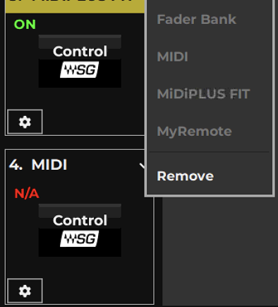
Open the Controls menu and select MIDI Controller.
Click on the Gear button on the MIDI control icon to open the MIDI control panel.
Show Control Section
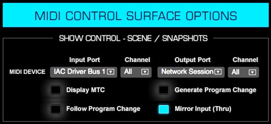
This section sets the MIDI port and channel used for triggering Scenes using MIDI program change messages.
Select a MIDI Device: Select an Input and Output port from the drop-down menu, where all available MIDI ports are listed. The selected device appears in the Port Name box.
The Classic console can receive MIDI from virtual MIDI protocols (such as rtpMIDI) over the console’s network port. Do not connect MIDI to a SoundGrid port. Download and install the driver. An rtpMIDI icon on the Kiosk’s Utilities tab indicates that the driver is installed and running.
Choose a MIDI Channel: Select a MIDI channel for Input and Output.
Assigning a Specific (single) channel (when applicable) means that all data from other channels are filtered out from the incoming stream. Messages that are part of the stream and are common to all channels will remain in the stream.
Select the All Channels option and all the channels will remain in the stream; none will be filtered. The incoming stream is unchanged.
Follow Program Change: When selected, scene changes can be controlled by MIDI program change commands from the device on the selected input port and channel. Scenes changes are based on the Scene index numbers. The Scene index number reflects its position in the Scenes List (on the Show window).
For example:
Program A: MIDI control change messages 0–127 > Scenes 1–128 Program B: MIDI control change messages 0–127 > Scenes 129–256 Program C: MIDI control change messages 0–127 > Scenes 257–384
Program D: MIDI control change messages 0–127 > Scenes 385–512 The mixer supports up to 1000 scenes.
When Follow Program Change is selected, the MIDI indicator in the Scenes window is illuminated. Follow Program Change can be activated from either window.
Generate Program Change: Selecting this option for the MIDI output sends a Program Change command whenever a Scene is recalled. The program change number follows the Scene index number.
Display MTC: When selected, the time window in the Top Bar displays MIDI timecode. When deselected, the window displays time from the console’s computer.
Mirror Input (Thru): When selected, the input stream is sent directly to the selected output port without changes.
Mixer Remote
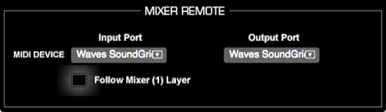
This section sets the port that the MIDI controller will use to map the mixer. The 16 faders in each layer are mapped to standard MIDI mapping: volume, pan, and mute controls for each fader.
Input Port/Output Port: Select MIDI Ports. Selection can be set for a specific port only.
Follow Mixer Window: When Follow Mixer Window is selected, the MIDI faders will map the faders of the selected Layer, as displayed in the Mixer window. For example, when Mixer Layer 17–32 is selected, MIDI channel 1 will control mixer channel 17. When AUX/FX is selected, MIDI Channel 1 will control AUX/MON 1.
When Follow Mixer Window is off, the mixer and the controller are independent of each other.
Using a SoundGrid I/O device as a MIDI port: A SoundGrid I/O device with a MIDI port can be assigned to the SoundGrid MIDI driver. This device can then be used as a MIDI port for the mixer, and as an I/O.
C: MyRemote
Waves mobile apps enhance flexibility and efficiency when setting up and managing live sound events. These apps connect to eMotion LV1 Classic via a private, dedicated Wi-Fi network. Open the mobile apps in the MyRemote control panel. Click the Gear icon to open it.
Waves Mobile Apps
MyMon | Allows each musician to control a dedicated aux mix. Compatible with eMotion LV1 and SoundGrid Studio. Compatible with phones and tablets. |
MyFOH | Allows basic remote control over eMotion LV1 mixer by FOH engineer. Compatible with eMotion LV1. Compatible with tablets only. |
mRecall | Allows remote recall of preprogrammed Scenes and Snapshots. Compatible with eMotion LV1 and SuperRack. Compatible with phones and tablets. |
MixTwin | Efficiently mirrors and optimizes your mixer window onto your tablet device.
|
Mobile Apps Setup - LV1 Side
- Run a dedicated Ethernet cable from the LV1 host computer to the Wi-Fi router. This connection provides control information for the mobile apps Wi-Fi network. No audio passes over it. Do not run the mobile apps network over the SoundGrid network. If the host computer does not have a second Ethernet port, use a USB-to-Ethernet (or other) adaptor. While it is possible to place the Wi-Fi router at the FOH position, we recommend placing it near the mobile clients.
- Launch eMotion LV1 and go to Setup Window > System Inventory Page > Controls column.
- Click on an empty Control slot and select MyRemote from the menu. The MyRemote icon will appear in the slot. Open the MyRemote control panel by clicking on the Gear button. A single MyRemote Control module provides simultaneous communication between the host and all four mobile apps.
Install Mobile Apps on a Device
- Install the Mobile Apps of choice (MyMon, MyFOH, mRecall, MixTwin [iPad only]). These apps can be installed for free from the following sources:
- Android phone/tablet users: Google Play
- iPhone/iOS tablet users: App Store
- Establish a Wi-Fi name and password protect your Wi-Fi network. Share the Wi-Fi network name and password with all mobile clients. All users can now connect to the mobile apps Wi-Fi network in their mobile devices and launch the app.
- The app will automatically detect the Host computer. Select the host and click Connect.
- The MyRemote control panel on the host displays the name of the newly connected mobile device and the app used to connect to the mobile apps network.
MyRemote Control Panel
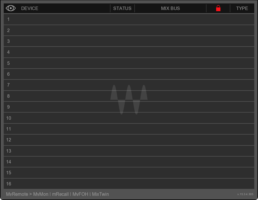
The Control Panel presents a blank table. When mobile devices are installed, the table becomes populated. Devices are named on the left, then the mix bus being sent to the device, and finally, the mobile device name.
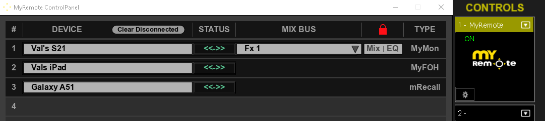
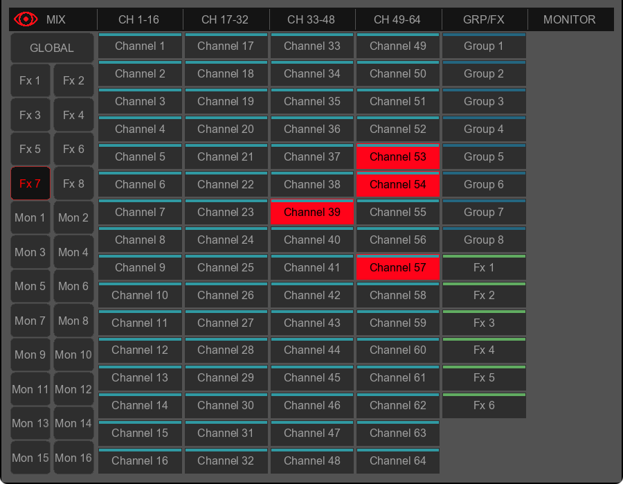
A grid enables the FOH to select specific mix buss channels and lock them to prevent the artist from adjusting them.
D: Delay Groups
eMotion LV1 can host plugins on every channel and buss. Different channels will likely use different plugins, each of which can impose different delays. At points where channels or busses are summed, they must be aligned with each other as a group. Those with the least delay are aligned to those with the greatest delay. Summing to a buss does not add delay but adding plugins to the buss may introduce delay. When these busses are again summed, delay adjustment may again be needed. This is latency compensation.
The output to the Main L/R will have a certain delay (compared to the input) because of A>D converters, network buffers, and the latency compensation introduced by plugins latencies throughout the Main L/R mix. However, busses routed to different I/Os do not necessarily need to be aligned with all other busses. Their delay alignment can be controlled as separate groups. These are Delay groups.
To create multiple delay groups, the mixer must be set to Delay Groups. This is done on the Mixer Settings page (Settings > Mixer Settings > Delay Compensation). Delay groups are assigned in the External Assignments section of the Channel window or in the Patch window. Refer to the Setup chapter of this manual or further details.
Set Mixer Latency Behavior
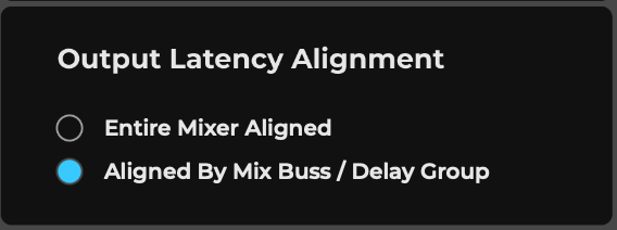
When using the mixer to produce latency critical outputs (e.g., for a monitor mix), it is advisable to use Delay Groups mode. This provides output compensation per mix buss, so high latency busses will not affect low latency ones.
The Output Delay Behavior Box determines how delay compensation will be managed.
- Entire Mixer: Total delay is the same throughout the mixer. All I/Os are aligned to the buss with the greatest delay. The user cannot create separate delay groups in this mode.
- Multiple Delay Groups: Enables I/Os to be assigned to separate delay groups. The I/Os that make up a delay group will be aligned and delayed together.
Latency, Delay Compensation, and Delay Groups
The delay added by the delay compensation function is determined by the various paths its signal can take. In the example below, Channels 1, 3, and 5 have plugins with different latencies. (Channel 1 = 100 samples; Channel 3 = 1000 samples; Channel 5 = 10 samples)
- Channels 1 and 3 are summed on the group buss and aligned to match the channel with the greatest latency (in this case, Input Channel 3). The group buss has its own plugins, which add another 50-sample delay. Buss latency is now 1050 samples.
- Channel 5 is routed to Main L/R, AUX/FX 1, and AUX/MON 1.
- AUX/MON 1 is sent directly to an I/O. No plugins are used on the buss. Since the signal is not summed with another buss having higher latency, its latency remains 10 samples when it reaches the I/O. AUX/FX 1 is routed to Main L/R.
- Three busses are sent to the Main L/R: AUX/FX 1, Group 1, and Input Channel 5. These busses must be delay compensated to match the delay of the buss with the greatest latency. So, the L/R output has a latency of 1050 samples.
- There are two I/Os, one with a latency of 1050 samples and the other with a latency of 10 samples. If you want to align these two I/Os, you can do so manually or by adding them to the same delay group.
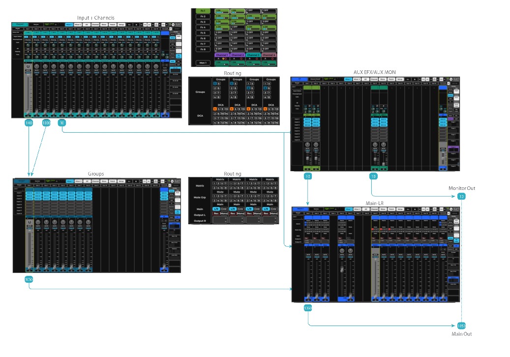
It is important to take into consideration plugins of different latencies when planning a signal flow.
Some groups of I/Os will need to be time aligned Proper planning can help avoid unnecessary delay compensation.
Assigning an I/O to a Delay Group: Channel Window Delay groups are assigned in the Output section of the Channel window. If you have not already done so, assign I/Os to the channel outs.
- Use the drop-down Delay Groups menu to assign the selected I/O channel to a delay group.
- Use the On/Off button to temporarily disengage a channel from the delay group. This does not remove the I/O from the delay group. Instead, it removes the plugin from plugin/buss latency compensation calculations.
- Drag up and down over the Delay value box to add delay. The box indicates the group’s delay value. Outputs that do not need to be assigned to a delay group can be set to None in the Delay Group menu. These outputs can be independently delayed by a user-defined value.
There is no limit to the number of I/Os that can be assigned to a delay group.
When the mixer is set to Entire Mixer latency compensation mode, the delay group menu will show “Entire Mixer.” This mode automatically adds all the assigned output I/Os to a single delay group, so that all mixer outputs will always be aligned.
Assigning an I/O to a Delay Group: Patch Window
You can also use the Patch window to assign I/Os to delay groups and set the delay value. Patch a delay group to any number of I/O channels. The group’s delay is noted in its value box and can be adjusted as in the Channel window.
This delay value matches the value in the Channel delay section Turning Off Plugin Compensation on Specific Plugins
You can turn off delay compensation for specific plugins in a rack. This can be useful when one or more plugins have very high latencies and you don’t want to delay the entire rack to compensate. When the source for a plugin is not time-critical (e.g., audience or ambience input), you can exclude this plugin from the delay compensation function by selecting Latency Compensation OFF in the Rack plugin menu. The plugin remains active, but its latency is no longer reported to the delay compensation engine.
Mode or Section All Alt+click on a control Returns most controls to default value. This is also true with most plugins.
Mixer Rack Alt+right click/insert a plugin The selected plugin is inserted in the same rack insert position on all channels in the layer.
Mixer Rack Alt+right click/bypass a plugin Bypasses all plugins in the same rack insert position on all channels in the layer. This affects the chosen rack position, regardless of the plugin type.
Mixer Rack Alt+right click/disable a plugin Disables all plugins in the same rack insert position on all channels in the layer. This affects the chosen rack position, regardless of the plugin type.
Mixer Rack Alt+right click/remove a plugin Removes all plugins in the same rack insert position on all channels in the layer. This affects the chosen rack position, regardless of the plugin type.
Mixer Rack Ctr+click on plugin icon Disable plugin.
Mixer Rack Ctrl+Alt+click on plugin icon Bypass plugin.
Mixer/Channel Ctrl+move image rotator vertically Changes width of image without rotating.
Mixer Aux Ctrl+click on mini aux send above bar Switches between aux sources.
Channel/Rack Ctrl+click on plugin icon Disables plugin.
Channel/Rack Ctrl+Alt+click on plugin icon Bypasses plugin.
E: Keyboard Shortcuts
Window | Mode or Section | Keystroke | Action |
|---|---|---|---|
All | All | Alt+click on a control | Returns most controls to default value. This is also true with most plugins. |
Mixer | Rack | Alt+right click/insert a plugin | The selected plugin is inserted in the same rack insert position on all channels in the layer. |
Mixer | Rack | Alt+right click/bypass a plugin | Bypasses all plugins in the same rack insert position on all channels in the layer. This affects the chosen rack position, regardless of the plugin type. |
Mixer | Rack | Alt+right click/disable a plugin | Disables all plugins in the same rack insert position on all channels in the layer. This affects the chosen rack position, regardless of the plugin type. |
Mixer | Rack | Alt+right click/remove a plugin | Removes all plugins in the same rack insert position on all channels in the layer. This affects the chosen rack position, regardless of the plugin type. |
Mixer | Rack | Ctr+click on plugin icon | Disable plugin. |
Mixer | Rack | Ctrl+Alt+click on plugin icon | Bypass plugin. |
Mixer/Channel | Ctrl+move image rotator vertically | Changes width of image without rotating. | |
Mixer | Aux | Ctrl+click on mini aux send above bar | Switches between aux sources. |
Channel/Rack | Ctrl+click on plugin icon | Disables plugin. | |
Channel/Rack | Ctrl+Alt+click on plugin icon | Bypasses plugin. |
Chapter 10: SPECIFICATIONS
eMotion LV1 Classic Live Mixer Product Hardware Specifications.
Sample Rate | 44.1 kHz, 48 kHz, 88.2 kHz, 96 kHz |
Processing | SoundGrid DSP server Double Precision 32 Bit Float |
Microphone / Line input |
+/- 0.1 dB, 20 Hz to 20 kHz +/ -1.0 dB, 10 Hz to 40 kHz
XLR: 2k ohms / 7k ohms, selectable per input TRS: 14.6k ohms
XLR: -33 dBu to +27 dBu, adjustable in 1 dB steps TRS: -27 dBu to +33 dBu, adjustable in 1 dB steps
|
Line output |
+/- 0.1 dB, 20 Hz to 20 kHz @ 48 kHz SR +0.1 / -1.0 dB, 10 Hz to 40 kHz @ 96 kHz SR
|
Phones output |
+/- 0.1 dB, 20 Hz to 20 kHz @ 48 kHz SR +0.1 / -1.0 dB, 10 Hz to 40 kHz @ 96 kHz SR
|
AES3 |
|
Faders |
|
SoundGrid |
|
Network |
|
USB |
|
Display |
|
Lamp |
|
Power |
|
Operating Temperature |
|
Size W x D x H | 561 mm (w) x 561 mm (d) x 402 mm (h) 22.1 inch (w) x 22.1 inch (d) x 15.8 inch (h) |
Weight | 17.3 kg (38.1 lbs) |
Mechanical Diagram